Control system

A system pressure, compression system technology, applied in variable speed drives to improve performance at part loads, background art
The application generally relates to being used for having a first-level field, to achieve the effect of reducing complexity and improving system efficiency

Active Publication Date: 2010-09-22
JOHNSON CONTROLS TYCO IP HLDG LLP
View PDF7 Cites 18 Cited by
  • Summary
  • Abstract
  • Description
  • Claims
  • Application Information

AI Technical Summary

Problems solved by technology

Each of these capacity control met

Method used


Image

  • Control system
  • Control system
  • Control system

Examples


Embodiment Construction

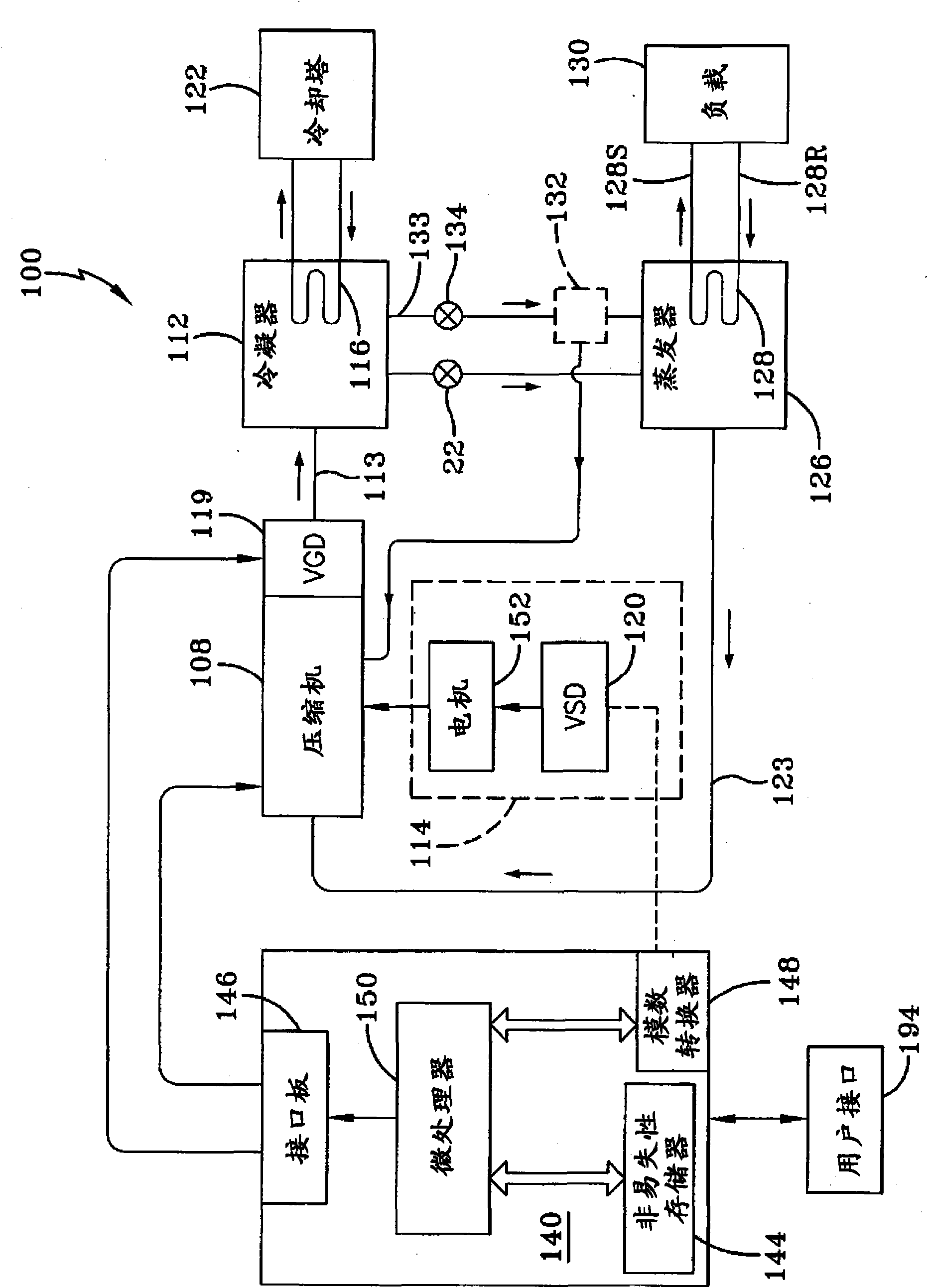
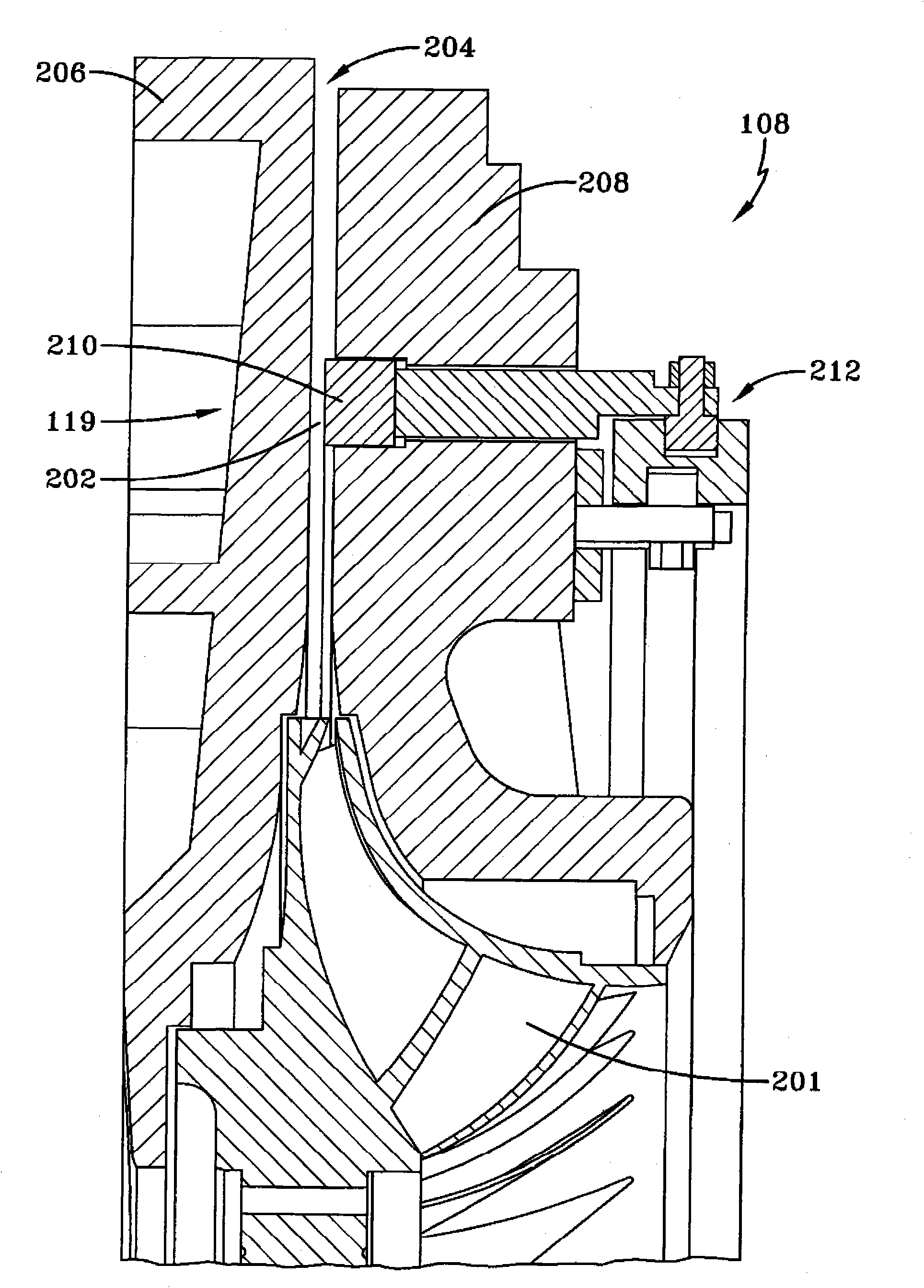
[0024] exist figure 1 In, a general HVAC & R chiller system 100 is shown by way of example, to which the present invention is applicable. An HVAC & R system 100 for controlling, for example, a centrifugal gas compressor 108 in an HVAC & R or liquid cooler system 100 is described below. Compressor 108 may be a single-stage or multi-stage centrifugal compressor. The flow of refrigerant gas through compressor 108 is automatically controlled to maintain desired parameters within predetermined ranges and prevent stall and surge conditions within system 100 . The VGD 119 in each stage of the compressor 108 controls the impeller 201 of the compressor (see figure 2 ) refrigerant flow at the outlet. The VGD 119 arrangement reduces mass flow, reduces or eliminates flow reduction stall, and improves the operating efficiency of compressor 108 when operating at part load conditions. Capacity control through the use of a variable geometry diffuser in conjunction with a variable speed d...


PUM


Abstract

A system for controlling a centrifugal gas compressor (108) in an HVAC, refrigeration or liquid chiller system (100) in which flow of gas through the compressor is automatically controlled to maintain desired parameters within predetermined ranges so as to prevent stall and surge conditions within the system. A variable geometry diffuser (119) in the compressor controls the refrigerant gas flow at the discharge of the compressor impeller wheel (201). This arrangement reduces mass flow, decrease/eliminate flow-reducing stall, and increases the operating efficiency of the compressor at partial load conditions. The variable geometry diffuser control in combination with a variable speed drive (VSD) (120) increases the efficiency of the compressor at partial system loads, and eliminates the need for pre-rotation vanes at the inlet of the centrifugal compressor.

Description

[0001] Cross References to Related Applications [0002] This application claims priority and benefit to US Provisional Application No. 60 / 984,073, filed October 31, 2007, entitled "VARIABLEGEOMETRY DIFFUSERS AS CAPACITY CONTROL," which is hereby incorporated by reference. Background technique [0003] The present application generally relates to capacity control systems for centrifugal compressors having one or more stages. The present application relates more particularly to a capacity control system for a compressor having a variable geometry diffuser (VGD). In refrigeration systems, capacity refers to cooling capacity, while in other gas compression systems, capacity refers to volumetric flow. [0004] Previously, in centrifugal compressors used in cooling systems such as liquid coolers, refrigeration or HVAC & R, and gas compression, pre-rotation vanes (PRV) or inlet guide vanes were required to control cooling The cooling capacity of the system. At the inlet from the ...

Claims


Application Information

Patent Timeline
IPC IPC(8): F04D27/02F04D17/12F04D25/04F04D29/44F04D29/46
CPCF04D27/0261F04D29/444F04D27/0246Y02B30/741F04D27/0207F25B2600/0253F04D25/04F04D29/462F25B2600/0261F04D27/0284F04D17/12F25B1/053F05D2250/52Y02B30/70
Inventor S·T·萨默小J·特雷维尼奥F·伊恩库R·彻维尔E·J·斯麦德
Owner JOHNSON CONTROLS TYCO IP HLDG LLP
Why Eureka
Try Eureka