
Multi-disc brake

A technology of brakes and dynamic friction plates, which is applied to the types of brakes, axial brakes, and parts of brakes, etc., can solve the problems of limited fatigue stress increase range, fatigue fracture of brake half-shaft and half-shaft, and increased manufacturing costs, etc., to achieve Large braking torque, convenient maintenance, and the effect of reducing impact load

Inactive Publication Date: 2010-09-29
XIAMEN UNIV
View PDF3 Cites 3 Cited by
  • Summary
  • Abstract
  • Description
  • Claims
  • Application Information

AI Technical Summary

Problems solved by technology

[0003] Most domestic wet multi-disc brakes achieve braking through the braking half shaft (such as Chinese patent ZL200720311907.5), but in the case of meeting the design requirements, in actual use, the braking half shaft will experience half shaft fatigue fracture conditions, and cause the vehicle to be unable to brake and cause accidents, especially in the field of construction machinery with more complicated working conditions
Fatigue damage is generally caused by poor working conditions and frequent braking. The traditional solution is to increase the diameter of the half shaft, replace the material of the half shaft, and change the heat treatment process of the half shaft. However, this method not only increases the manufacturing cost, but also The increase range of fatigue stress is also relatively limited, and this phenomenon cannot be effectively controlled, causing certain safety hazards to the operator.

Method used


Image

  • Multi-disc brake
  • Multi-disc brake
  • Multi-disc brake

Examples


Embodiment Construction

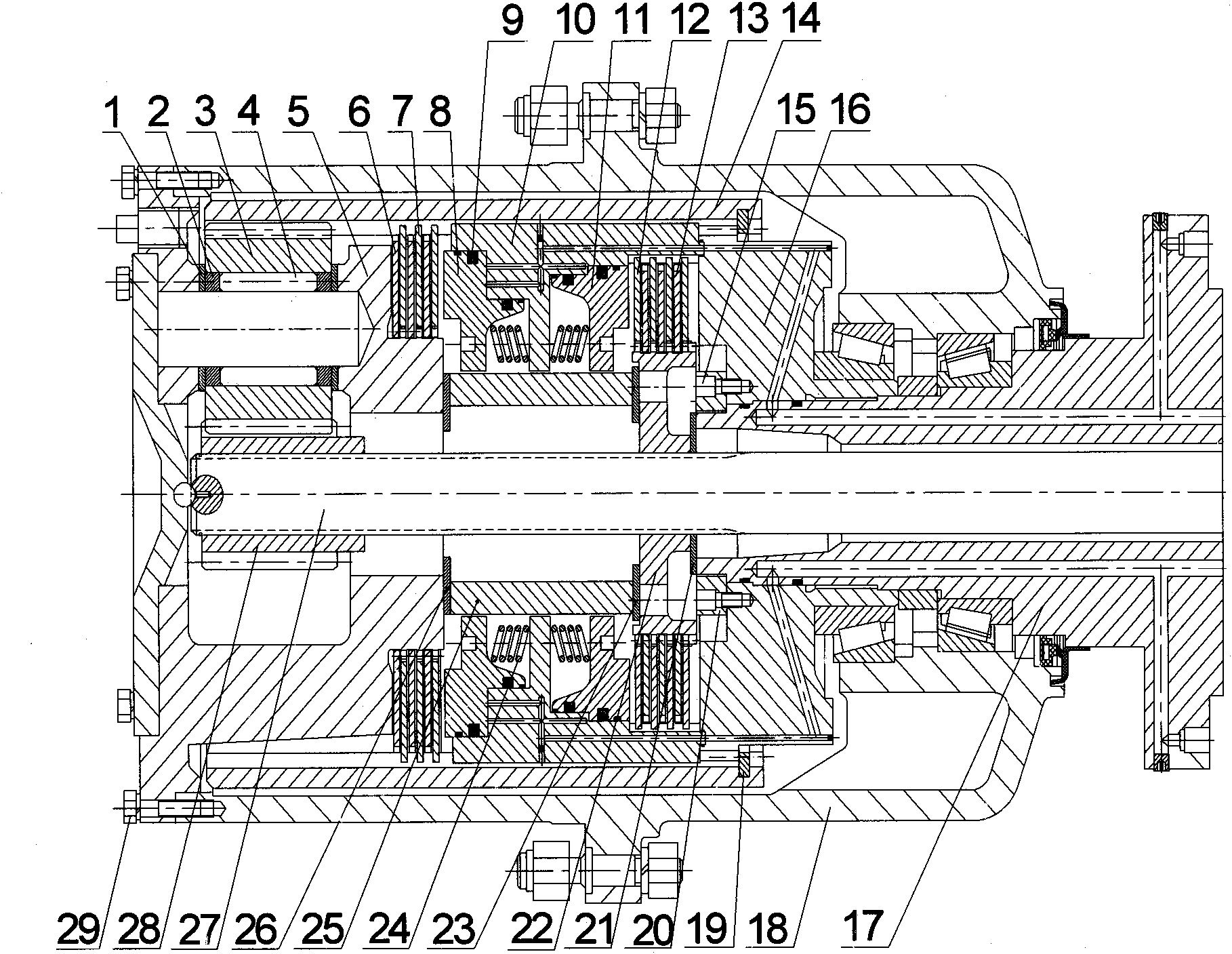
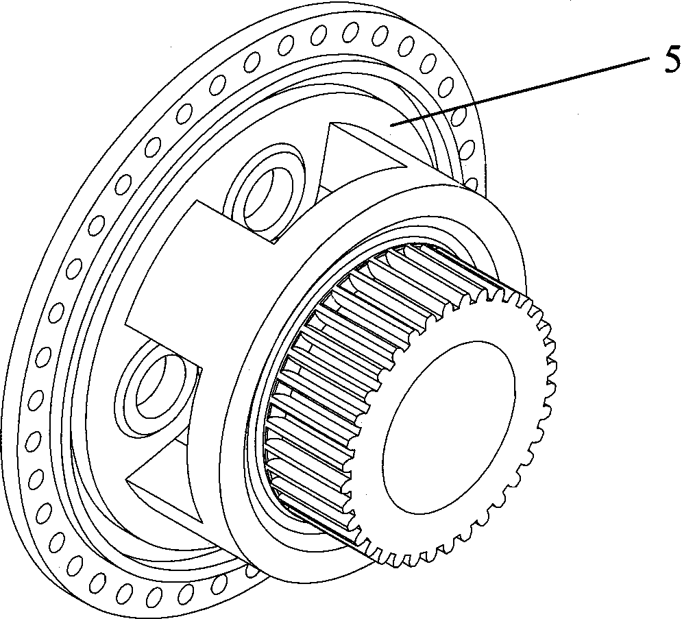
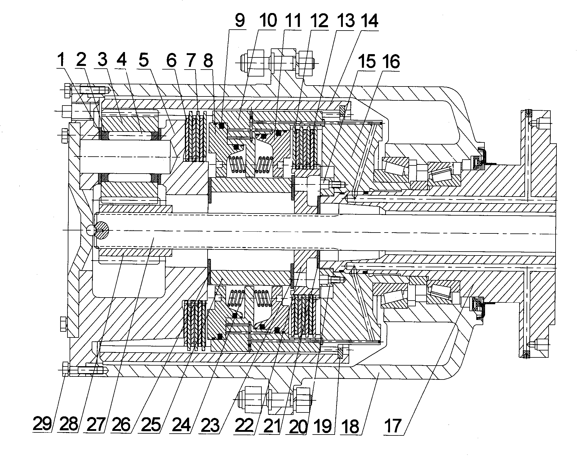
[0013] see figure 1 and 2 , the embodiment of the present invention is provided with left brake, right brake and piston bracket 10;

[0014] The left brake is provided with a planetary gear carrier 5, a left dynamic friction plate 6, a left static friction plate 7, a left piston 8, an inner ring gear 14 and a left return spring 241; the outer teeth of the left static friction plate 7 are connected with the inner teeth of the inner ring gear 14 , the inner teeth of the left moving friction plate 6 are connected with the outer teeth of the planetary gear carrier 5, the left moving friction plate 6 and the left static friction plate 7 are spaced apart and equal in number; the outer teeth of the piston bracket 10 are connected with the inner teeth of the ring gear 14, The left piston 8 is installed on the left side of the piston bracket 10, and the left return spring 241 is connected with the piston bracket 10 and the left piston 8 respectively.

[0015] The right brake is provi...


PUM


Abstract

The invention discloses a multi-disc brake, and relates to a vehicle brake. The multi-disc brake is provided with a left brake, a right brake and a piston bracket, wherein the left brake is provided with a planet wheel carrier, left movable friction sheets, left static friction sheets, a left piston, an internal tooth ring and a left return spring; external teeth of the left static friction sheets are connected with the internal teeth of the internal tooth ring; internal teeth of the left movable friction sheets are connected with external teeth of the planet wheel carrier; external teeth of the piston bracket are connected with the internal teeth of the internal tooth ring; the left piston is arranged at the left edge of the piston bracket; and the left return spring is respectively connected with the piston bracket and the left piston. The right brake is provided with a right piston, right static friction sheets, right movable friction sheets, an internal tooth ring, an internal tooth ring bracket and a right return spring; external teeth of the right static friction sheets are connected with internal teeth of the piston bracket; internal teeth of the right movable friction sheets are connected with external teeth of the fixed bracket; the total number of the right static friction sheets is one more than that of the right movable friction sheets; the right piston is arranged at the right edge of the piston bracket; the right return spring is respectively connected with the piston bracket and the right piston; and the internal tooth ring bracket is relatively static to a bridge shell.

Description

technical field [0001] The present invention relates to a vehicle brake, in particular to a multifunctional wet multi-disc braking device applicable to various vehicles including industrial vehicles. Background technique [0002] At present, the types of brakes in my country's construction machinery field mostly use caliper disc brakes. Although caliper disc brakes have stable braking performance, can withstand the influence of temperature, water immersion and vehicle speed to a certain extent, and have better resistance to recession, etc. Generally, there is only one piece of brake disc, which has the disadvantages of small friction area, high pressure per unit area, poor heat dissipation conditions, easy ablation, and short service life. With the continuous development of the construction machinery industry, the requirements for braking performance are getting higher and higher. In recent years, the multi-disc wet disc brake adopted by foreign countries has been more and mo...

Claims


Application Information

Patent Timeline
Patent Type & Authority Applications(China)
IPC IPC(8): F16D55/228F16D65/20F16D65/18
Inventor 侯亮刘才荣李淼
Owner XIAMEN UNIV
Learn More