Vacuum steam generating heat exchanger for wall-hung condensing gas furnace

A steam generator and heat exchanger technology, which is applied in thermal storage heaters, fluid heaters, lighting and heating equipment, etc. The method is uncontrollable and other problems, so as to avoid the burning of the water tank and reduce the corrosion effect.

Active Publication Date: 2010-09-29
YINCHUAN AINI IND TECH DEV
8 Cites 2 Cited by

AI-Extracted Technical Summary

Problems solved by technology

[0002] At present, the heat exchanger wall of the wall-hung boiler is directly heated by the flame, and the local high temperature of the water in the water pipe is easy to cause scale formation, especially in the use of high hardness water in the w...

Abstract

The invention relates to a wall-hung vacuum steam generator, in particular to a vacuum steam generating heat exchanger for a wall-hung condensing furnace, which is used for generating steam in the vacuum environment to exchange heat. The vacuum steam generating heat exchanger for the wall-hung condensing furnace integrates a heat exchanger and a vacuum steam generator and comprises a water return pipe, a steam output pipe, a water level observation window, a heat conduction flue gas pipe, a flue gas outlet joint pipe, a flue gas channel separation plate, a flue gas collection channel, a flue gas accumulation channel, a burner, a gas delivery pipe, medium water, a water cavity wall, a water cavity, a shell, heat exchanger blades, a heat exchanger pipe and a heat exchange cavity. The vacuum steam generating heat exchanger for the wall-hung condensing furnace is used for generating steam by heating the processed medium water in the vacuum environment in a circulatory way without treating the heated medium water, thus the scaling of the heat exchanger, the low heat exchange efficiency of the heat exchanger, the burndown of the water tank and other adverse consequences resulted from the scaling of the heat exchanger can be avoided, and the corrosion to the circulating system due to the treatment of the acid in the heated medium water can be reduced.

Application Domain

Storage heaters

Technology Topic

Cavity wallCorrosion +7

Image

  • Vacuum steam generating heat exchanger for wall-hung condensing gas furnace
  • Vacuum steam generating heat exchanger for wall-hung condensing gas furnace
  • Vacuum steam generating heat exchanger for wall-hung condensing gas furnace

Examples

  • Experimental program(1)

Example Embodiment

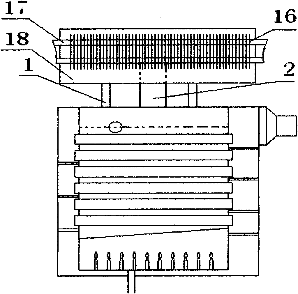
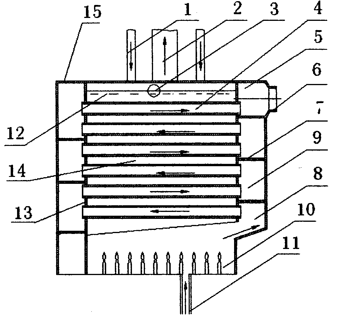
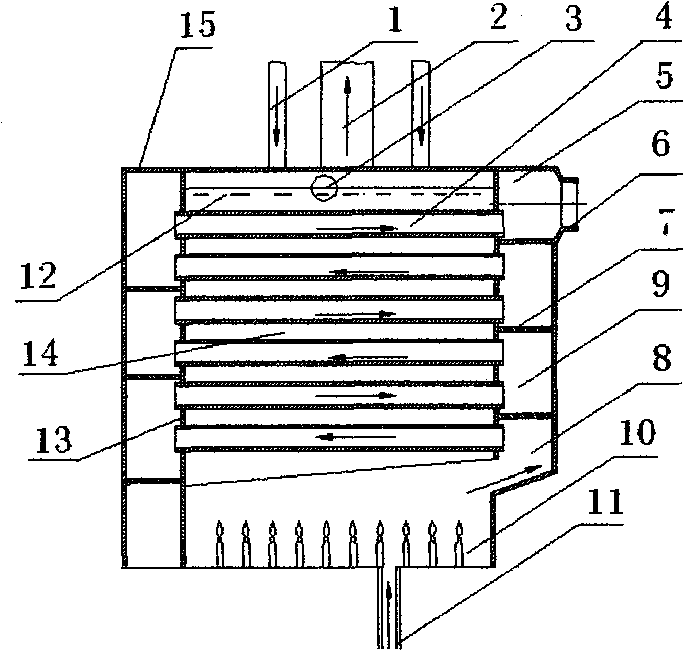
[0012] The vacuum steam generating heat exchanger for the condensing wall-hung boiler of the present invention includes a heat exchanger and a vacuum steam generator. It consists of a water return pipe 1, a steam output pipe 2, a water level observation window 3, a heat conducting smoke pipe 4, and a flue gas vent pipe 5. The flue gas outlet pipe 6, the flue gas channel partition 7, the flue gas collection channel 8, the flue gas collection channel 9, the burner 10, the gas delivery pipe 11, the medium water 12, the water cavity wall 13, the water cavity 14, the housing 15, the changer Heater blade 16, steam heat exchanger tube 17, and heat exchange cavity 18;
[0013] A. The heat exchanger is composed of water return pipe 1, heat exchanger blade 16, steam heat exchanger tube 17 and heat exchange cavity 18; the bottom of heat exchange cavity 18 is equipped with a water return pipe 1, and the other end of the water return pipe 1 is connected to the water cavity 14. A steam heat exchanger tube 17 is installed in the cavity of the hot cavity 18, and a heat exchanger blade 16 is installed on the steam heat exchanger tube 17;
[0014] B. The vacuum steam generator consists of steam output pipe 2, water level observation window 3, heat conduction smoke pipe 4, flue gas vent pipe 5, flue gas outlet pipe 6, flue gas channel partition 7, flue gas collection channel 8, smoke collection channel 9. The burner 10, the gas delivery pipe 11, the medium water 12, the water cavity wall 13, the water cavity 14, and the shell 15 are composed; a water cavity 14 is installed in the center of the shell 15, a burner 10 is installed at the bottom of the water cavity 14, and the burner 10 is connected to gas The conveying pipe 11, the upper end of the burner 10 is connected to the heat-conducting smoke pipe 4 through the flue gas collection channel 8. The heat-conducting smoke pipe 4 is installed on the outer water cavity wall 13 of the water cavity 14, and the smoke is fixed and assembled between two adjacent heat-conducting smoke pipes 4 The channel partition 7, one end of the flue gas channel partition 7 is consolidated with the water cavity wall 13, and the other end is consolidated with the housing 15. Every two adjacent heat conducting smoke pipes 4 and the flue gas channel partition 7 form a smoke collecting channel 9. The heat-conducting smoke pipe 4 at the uppermost end of the cavity wall 13 is connected to the flue gas outlet pipe 6 through the flue gas vent pipe 5; a steam output pipe 2 is installed at the top of the water cavity 14 and the steam output pipe 2 is connected to the heat exchange cavity 18. The water cavity 14 is filled with pretreatment medium water; the heat-conducting flue pipe 4 can be one or several, made of materials that can resist flue gas corrosion; the flue gas channel baffle 7 can be one or several , It is made of materials that can resist flue gas corrosion; the vacuum steam generator can be equipped with a steam output pipe 2 and a water return pipe 1, or it can be directly installed in the vacuum steam generator.

PUM

no PUM

Description & Claims & Application Information

We can also present the details of the Description, Claims and Application information to help users get a comprehensive understanding of the technical details of the patent, such as background art, summary of invention, brief description of drawings, description of embodiments, and other original content. On the other hand, users can also determine the specific scope of protection of the technology through the list of claims; as well as understand the changes in the life cycle of the technology with the presentation of the patent timeline. Login to view more.

Similar technology patents

Thick film photoresist detergent

InactiveCN101738880Aless corrosivereduce corrosion
Owner:ANJI MICROELECTRONICS (SHANGHAI) CO LTD

Synthesis method of polyamide polyamine resin

Owner:佛山市帕里达新材料科技有限公司

Classification and recommendation of technical efficacy words

Why Eureka
Try Eureka