Bipolar Null and Gain Adjustable Amplifier and Analog Signal Conditioner
A bipolar, amplifier technology, used in gain control, improving amplifiers to reduce temperature/power supply voltage changes, amplification control, etc. Bipolar positive and negative adjustable and other issues, to achieve the effect of reducing zero drift
- Summary
- Abstract
- Description
- Claims
- Application Information
AI Technical Summary
Problems solved by technology
Method used
Image
Examples
Embodiment 1
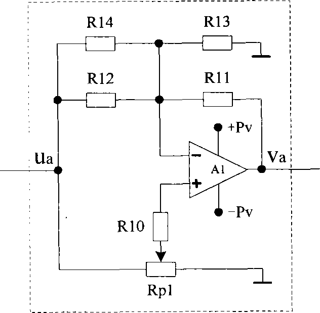
[0080] Voltage-mode bipolar gain-adjustable amplifiers (such as figure 1 As shown) has an input terminal ua and an output terminal va. The voltage-type bipolar gain adjustable amplifier is composed of an operational amplifier A1, a potentiometer Rp1, and resistors R10~R14. The non-inverting input terminal of the operational amplifier A1 is connected to the potential through the resistor R10 The sliding end of the potentiometer Rp1, one end of the two fixed ends of the potentiometer Rp1 is connected to the input end ua of the bipolar gain adjustable amplifier, and the other end is grounded, and the inverting input end of the operational amplifier A1 is connected through the parallel circuit of the resistors R12 and R14 The input terminal ua of the bipolar gain-adjustable amplifier is connected to the ground through the resistor R13, and the output terminal of the operational amplifier A1 is connected through the resistor R11, and the output terminal of the operational amplifier ...
Embodiment 2
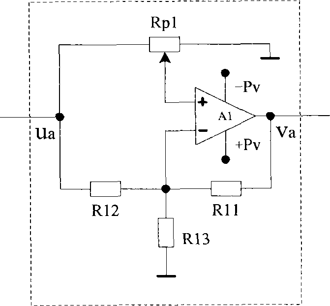
[0088] Compact bipolar gain-adjustable amplifiers such as figure 2 As shown) has an input terminal ua and an output terminal va. The simple bipolar gain adjustable amplifier is composed of operational amplifier A1, potentiometer Rp1, resistors R11, R12 and R13. The non-inverting input terminal of operational amplifier A1 is connected to the potentiometer The sliding end of Rp1, the two fixed ends of the potentiometer Rp1, one end is connected to the input end ua of the bipolar gain adjustable amplifier, and the other end is grounded, and the inverting input end of the op amp A1 is connected to the bipolar gain adjustable through the resistor R12 The input terminal ua of the amplifier is connected to the ground through the resistor R13, and connected to the output terminal of the operational amplifier A1 through the resistor R11, and the output terminal of the operational amplifier A1 is connected to the output terminal va of the bipolar gain-adjustable amplifier.
[0089] Tak...
Embodiment 3
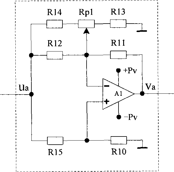
[0095] Current-mode bipolar gain-adjustable amplifiers (such as image 3 (shown) has an input terminal ua and an output terminal va. The current-type bipolar gain-adjustable amplifier is composed of an operational amplifier A1, a potentiometer Rp1, and resistors R10~R15. The non-inverting input terminal of the operational amplifier A1 is connected to the dual The input terminal ua of the polar gain adjustable amplifier is grounded through the resistor R10, the inverting input terminal of the op amp A1 is connected to the sliding terminal of the potentiometer Rp1, the input terminal ua of the bipolar gain adjustable amplifier is connected through the resistor R12, and passed through Resistor R11 is connected to the output terminal of operational amplifier A1, one end of the two fixed ends of potentiometer Rp1 is connected to the input terminal ua of the bipolar gain adjustable amplifier through resistor R14, and the other end is grounded through resistor R13, and the output term...
PUM
 Abstract
Description
Claims
Application Information
 - R&D
- Intellectual Property
- Life Sciences
- Materials
- Tech Scout
- Unparalleled Data Quality
- Higher Quality Content
- 60% Fewer Hallucinations
Browse by: Latest US Patents, China's latest patents, Technical Efficacy Thesaurus, Application Domain, Technology Topic, Popular Technical Reports.
© 2025 PatSnap. All rights reserved.Legal|Privacy policy|Modern Slavery Act Transparency Statement|Sitemap|About US| Contact US: help@patsnap.com


