Energy-saving efficient pneumatic motor

An air motor and motor technology, applied in industrial and mining workplaces and in the field of air motors, can solve problems such as low work efficiency and energy waste, and achieve the effect of improving work efficiency

Inactive Publication Date: 2010-10-06
JIKAI EQUIP MFG CO LTD
View PDF0 Cites 4 Cited by
  • Summary
  • Abstract
  • Description
  • Claims
  • Application Information

AI Technical Summary

Problems solved by technology

However, the working efficiency of the air motor is very low at present. The working efficiency of the general air motor is 20-40%. After the compressed air passes through the air motor, it is directly discharged into the atmosphere from the air outlet. These gases discharged from the air outlet also have a large Energy, the current air motor energy loss rate is about 80%, resulting in a great waste of energy

Method used


Image

  • Energy-saving efficient pneumatic motor
  • Energy-saving efficient pneumatic motor
  • Energy-saving efficient pneumatic motor

Examples


Embodiment 1

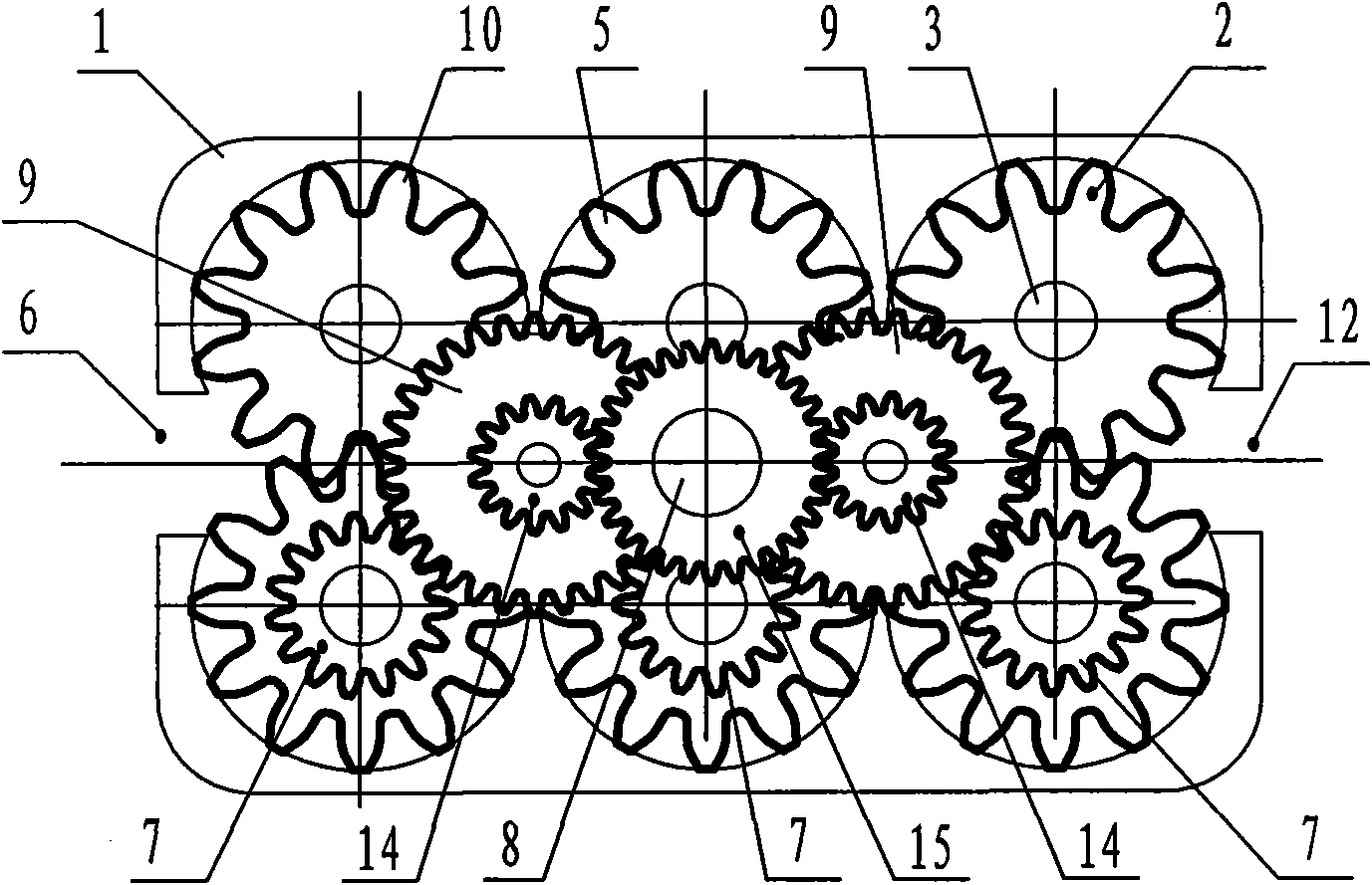
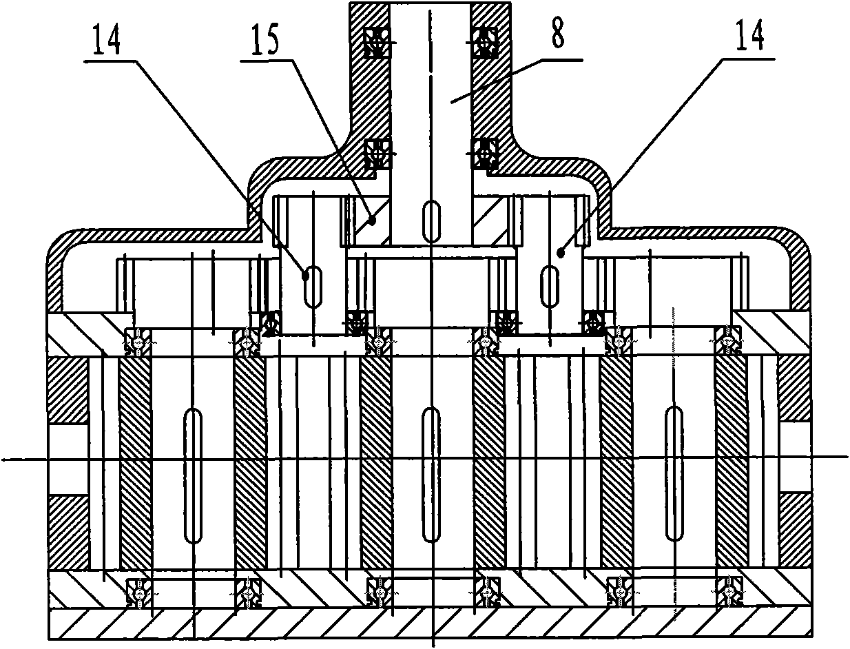
[0018] This example figure 1 , 2 As shown, the main body of the motor casing 1 is a strip shape, and one end of the motor casing 1 is provided with an air inlet 12 , and the other end is provided with an air outlet 6 . Three-stage motor gears are installed in the motor housing 1 , which are respectively a pair of first-stage motor gears 2 , a pair of second-stage motor gears 5 , and a pair of third-stage motor gears 10 . The modules from the first stage motor gear 2 to the third stage motor gear 10 increase step by step. Each motor gear is respectively installed in the motor housing 1 through the shaft 3, and the end of the shaft 3 of a motor gear of each stage of motor gear is fixed with a primary driving gear 7, and each primary primary driving gear 7 is connected to the primary stage. The passive gear 9 meshes, and the primary passive gear 9 is installed on the secondary driving gear shaft 14, the secondary driving gear shaft 14 meshes with the secondary passive gear 15, ...

Embodiment 2

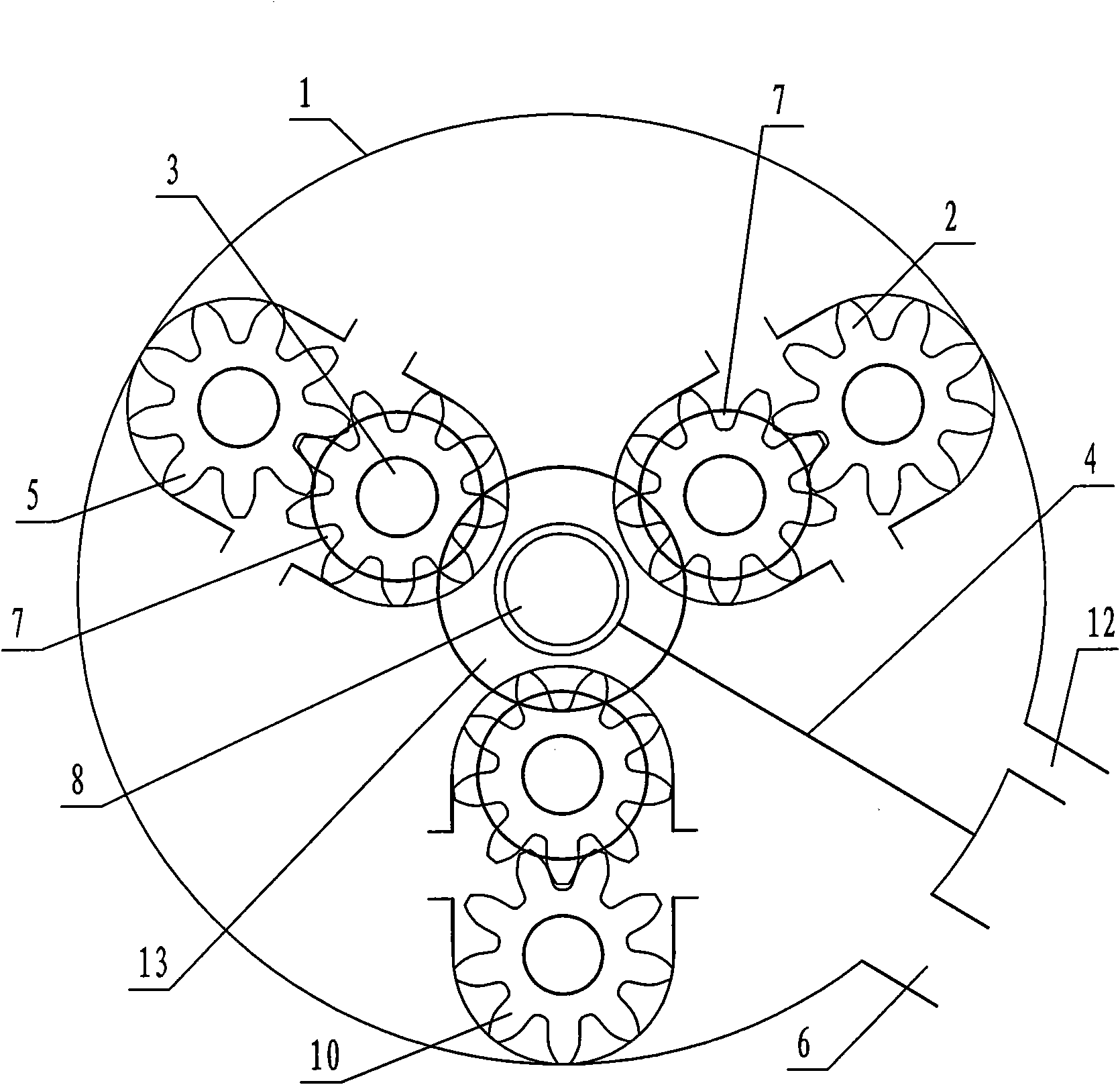
[0020] This example image 3 As shown, the main body of the motor housing 1 is circular, and three-stage motor gears are installed in the motor housing 1, which are respectively a pair of first-stage motor gears 2, a pair of second-stage motor gears 5, and a pair of third-stage motor gears. The modulus of the motor gear 10 increases step by step from the first stage motor gear 2 to the third stage motor gear 10 . Each motor gear is respectively installed in the motor housing 1 through the shaft 3. The center of the motor housing 1 is equipped with an output shaft 8, and each pair of motor gears surrounds the output shaft 8 in stages. Evenly distributed inside. The end of the shaft 3 of each motor gear is provided with a primary driving gear 7, and an output gear 13 is arranged on the output shaft 8. Each primary driving gear 7 meshes with the output gear 13 to form a linkage form. The output power is concentrated on the output shaft 8 for output. The air inlet 12 and the ex...


PUM


Abstract

The invention discloses an energy-saving efficient pneumatic motor, which is applied in industrial and mining workplaces. The energy-saving efficient pneumatic motor mainly comprises a motor shell (1), motor gears which are arranged in the motor shell (1) and an output shaft (8) which is connected with the motor gears and used for outputting power, the motor shell (1) is provided with an air inlet (12) and an exhaust port (6), the motor gears are arranged in the motor shell (1) in pairs at different levels, serial arrangement is adopted for motor gears of each level, and the motor gears of each level are connected with the output shaft (8) used for outputting the power through transmission gears. The modulus of the motor gears of different levels increases gradually. The invention fully utilizes the energy of the compressed air, and minimizes the energy of the exhaust gas out of the pneumatic motor. Since the energy of the compressed air is fully utilized, the invention improves the working efficiency of the pneumatic motor.

Description

technical field [0001] The invention relates to an air motor, which belongs to the field of mechanical engineering and is applied to industrial and mining workplaces. Background technique [0002] Air motor is a kind of mechanical equipment powered by compressed air. It is widely used and necessary in places where electricity is not allowed as power. The structure of the air motor has many forms, including gear type, piston type, vane type, turbine type, but the gear type air motor is the most widely used in industries such as coal mines. The geared air motor is equipped with a pair of intermeshing gears inside the housing, and the gear shaft of one of the gears is the power output shaft, which is connected with the reducer and other equipment. The two sides of the housing of the geared air motor are respectively provided with an inlet and an outlet of compressed air. When the compressed air passes through the geared air motor, the gears are driven to rotate at a high speed...

Claims


Application Information

Patent Timeline
Patent Type & Authority Applications(China)
IPC IPC(8): F01C1/16
CPCF01C1/12F01C17/02F01C11/002F01C1/18F01C20/02
Inventor 冯春保王树盘
Owner JIKAI EQUIP MFG CO LTD
Why Eureka
Try Eureka