Ultrathin LED backlight module

A backlight module, ultra-thin technology, applied in the field of ultra-thin LED backlight modules, can solve difficult problems

Active Publication Date: 2010-10-06
河源鑫智胜电子有限公司
View PDF6 Cites 3 Cited by
  • Summary
  • Abstract
  • Description
  • Claims
  • Application Information

AI Technical Summary

Problems solved by technology

[0004] In the prior art, the development trend of various electronic display products is towards the direction of thinning. The products have the advantages of small size, light weight, convenient installation, portability and maintenance. To ensure the effect of display functions and maintain the concept of environmental protection and energy saving of LED products, it is very difficult to design each electronic product to be ultra-thin

Method used


Image

  • Ultrathin LED backlight module
  • Ultrathin LED backlight module
  • Ultrathin LED backlight module

Examples


Embodiment 1

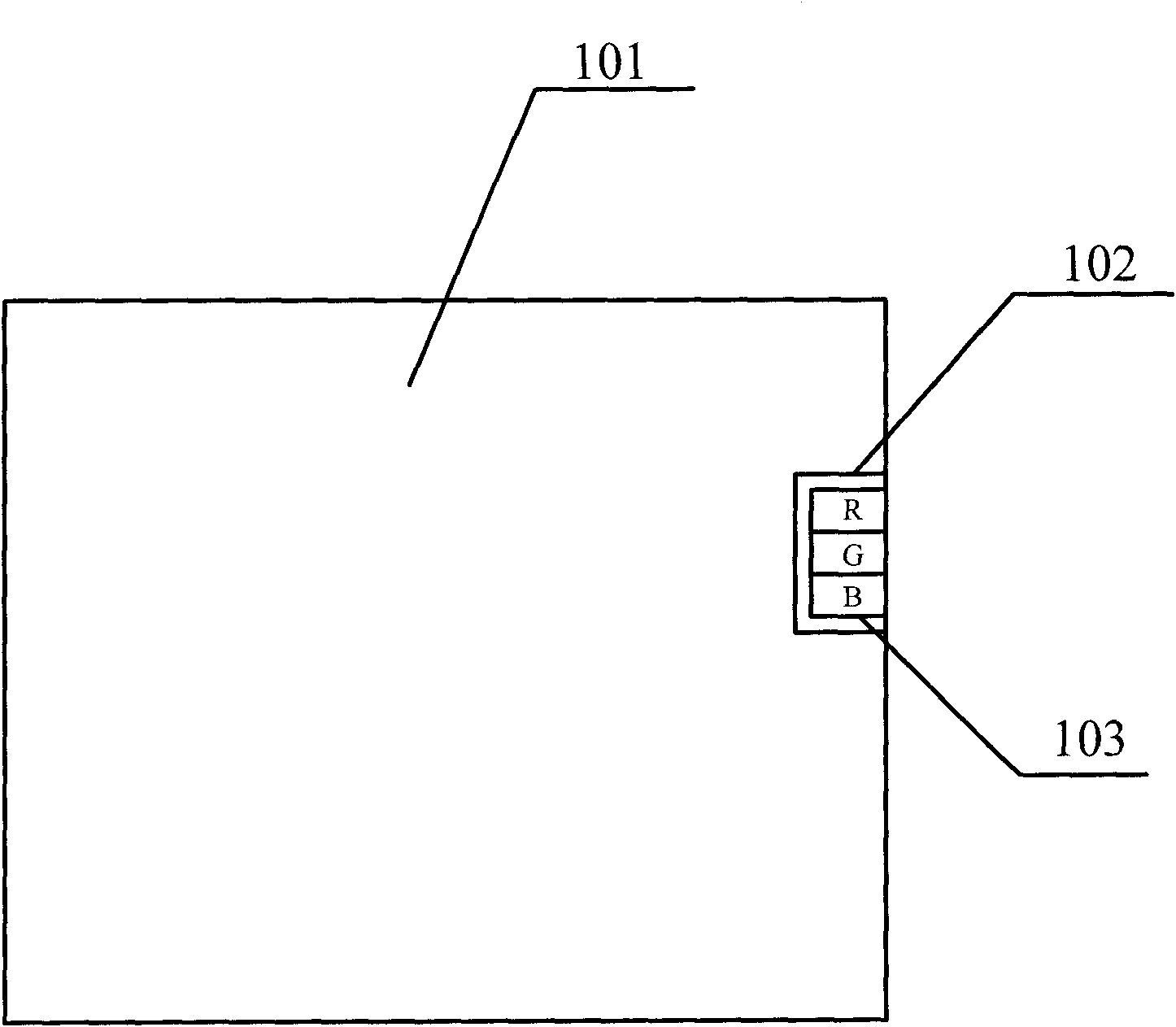
[0024] like figure 1 As shown, this embodiment provides an ultra-thin LED backlight module, wherein the ultra-thin backlight module includes several LEDs 103 and one or more light guide plates, such as one light guide plate 101 .

[0025] Each LED 103 includes one or more red LED thin film chips R, one or more green LED thin film chips G and one or more blue LED thin film chips B, for example, including one red LED thin film chip R, one green LED thin film chip G and a blue LED film chip B, or include a red LED film chip R, two green LED film chips G and a blue LED film chip B.

[0026] Moreover, the LED thin film chips in each LED 103 are connected side by side to form a polygon. For example, the LED thin film chips are connected side by side in a straight line to form a rectangle, or connected side by side to form a triangle, or a circle, etc.; The thickness of one LED thin film chip can be the same or different, and the shapes and sizes of LED thin film chips of different ...

Embodiment 2

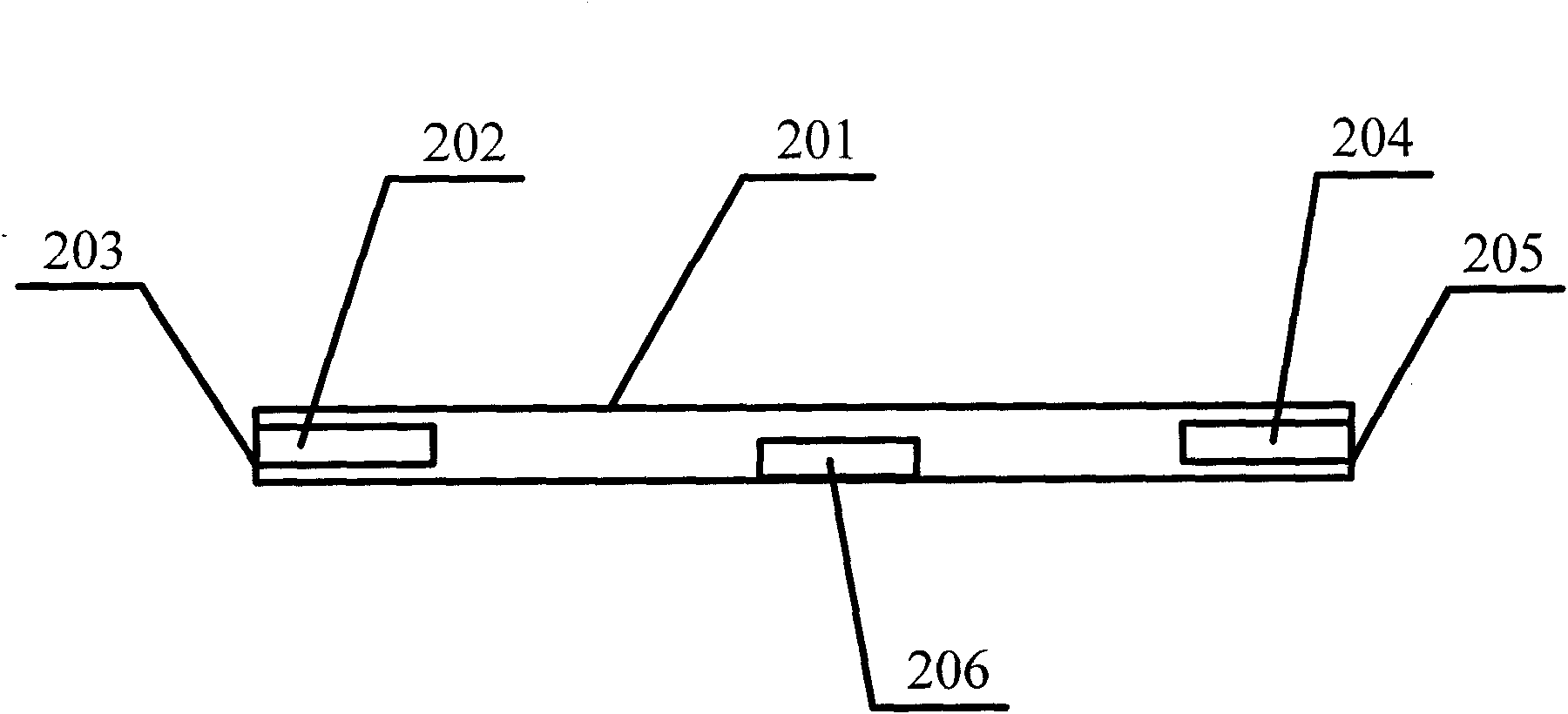
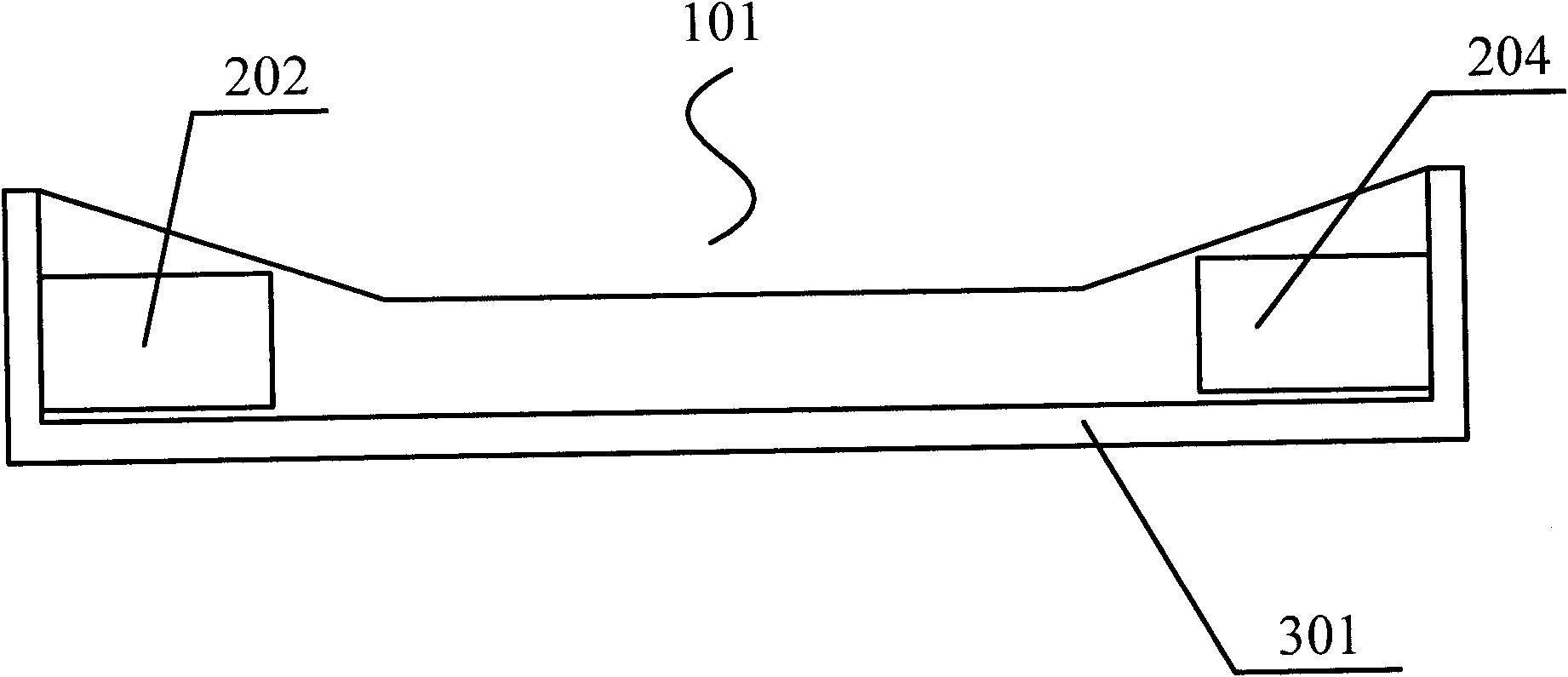
[0031] like figure 2 As shown, on the basis of the above examples, in the ultra-thin LED backlight module provided by this embodiment, LEDs are embedded in two or more sides of the light guide plate, for example, on the light guide plate LED202 is set on the side 203 of the light guide plate, LED202 is embedded in the light guide plate, LED204 is set on the side 205 of the light guide plate, LED204 is also embedded in the light guide plate, and the side 203 and side 205 are The opposite sides of the light guide plate, in this way, can make the distribution of the LEDs more uniform, and the light guide uniformity is good. For example, when the light guide plate is quadrilateral, rectangular, square or parallelogram, the LEDs are respectively located on two non-adjacent sides.

[0032] Moreover, when each LED is embedded in the light guide plate, it is parallel to the light guide surface 201 of the light guide plate, that is, the thickness direction of each LED is consistent w...

Embodiment 3

[0035] On the basis of the above examples, in the ultra-thin LED backlight module provided by this embodiment, the thickness of each LED film chip is set to 0.1mm-0.5mm, and preferably 0.3mm-0.4mm, ensuring that the LED The thickness of the thin-film chip is set to be the smallest, the luminous brightness per unit area is the strongest, and the number of P-N junctions set in each LED thin-film chip is the most reasonable. For example, the thicknesses of the LED thin film chips are respectively or both set to 0.1mm, 0.12mm, 0.15mm, 0.21mm, 0.24mm, 0.25mm, 0.36mm, 0.38mm, 0.385mm, 0.396mm, 0.399mm, 0.41mm, 0.5mm wait. For different light guide plates, the thickness of the LED film chip is set according to different product requirements.

[0036]Moreover, the ratio of the thickness of the LED to the thickness of the light guide plate is 0.8:1-1:1, because when the thickness of the light guide plate is greater than or equal to the thickness of the LED, the utilization rate of the...


PUM


Abstract

The invention discloses an ultrathin LED backlight module, which comprises a plurality of LEDs and at least one light guide plate, wherein each LED comprises at least one red LED thin film chip, at least one green LED thin film chip and at least one blue LED thin film chip, all LED thin film chips are connected in parallel for forming a polyhedron, each LED also comprises an encapsulation body with the same shape as the polyhedron, the encapsulation bodies are used for integrally encapsulating the LED thin film chips with each color, in addition, scattering film layers are arranged on the surfaces of the encapsulation bodies, the LEDs are embedded and arranged in the light guide plate, in addition, the ratio of the thickness of the LEDs to the thickness of the light guide plates is 0.6 / 1 to 1 / 1. The invention has the advantages of thin thickness, high light ray utilization rate, uniform light rays of the light guide plate and good light guide effect.

Description

technical field [0001] The invention relates to an LED lighting device, in particular to an ultra-thin LED backlight module. Background technique [0002] With the development of society, flat-panel displays will become more and more popular, especially in the TV field. The development trend of LCD TVs is already obvious. In the future, LCD TVs will become the leading role of large-screen flat-panel TVs. [0003] LEDs have long been used as backlights in small-sized LCD screens, such as 1.5-inch to 7-inch screens such as mobile phones, PDAs, PMPs, and GPSs. Now they are gradually developing into larger-sized screens to erode the CCFL market. For example, the LCD backlight of notebook computers has begun to be gradually replaced by LEDs. In the application of these small screens, most of them directly use white LEDs as backlights. Compared with CCFLs, LEDs have many significant advantages, such as no mercury, long life, large brightness adjustment range, large contrast, and ...

Claims


Application Information

Patent Timeline
Patent Type & Authority Applications(China)
IPC IPC(8): F21S8/00F21V8/00F21V19/00F21V17/00F21V29/00F21V13/00H01L25/075F21Y101/02F21V29/60F21V29/70
Inventor 商松
Owner 河源鑫智胜电子有限公司
Why Eureka
Try Eureka