
Automatic light beam capturing device and light beam capturing method

An automatic capture and beam technology, applied in the field of communication, can solve the problems of inconvenient optical-mechanical-electrical integration, uncompact structure, unsuitable for ground atmospheric laser communication systems, etc., and achieve the effect of convenient optical-mechanical-electrical integration and compact overall structure

Inactive Publication Date: 2010-10-06
XIAN UNIV OF TECH
View PDF3 Cites 16 Cited by
  • Summary
  • Abstract
  • Description
  • Claims
  • Application Information

AI Technical Summary

Problems solved by technology

[0003] The purpose of the present invention is to provide an automatic light beam capture device, which solves the problem that the existing beam capture device separates the beacon light and the signal light, the system structure is not compact, it is not convenient for optical, mechanical and electrical integration, and it is not suitable for the ground atmospheric laser communication system.

Method used


Image

  • Automatic light beam capturing device and light beam capturing method
  • Automatic light beam capturing device and light beam capturing method
  • Automatic light beam capturing device and light beam capturing method

Examples


Embodiment Construction

[0028] The present invention will be described in detail below in conjunction with the accompanying drawings and specific embodiments.

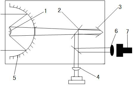
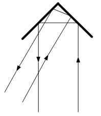
[0029] The structure of the beam automatic capture device of the present invention, such as figure 1 As shown, it includes an optical antenna 1 connected with an automatic tracking system 5, a Brinell window 2 and a corner reflector 3 are arranged on the outgoing light side of the optical antenna 1 in sequence, and a focusing lens 6 is arranged on the reflected light side of the Brinell window 2 in sequence And a signal detector 7, a position-sensitive detector 4 is arranged on the exit light side of the Brinell window 2, and the position-sensitive detector 4 is connected with the automatic tracking system 5 through a feedback channel.

[0030] The optical antenna 1 is used to collimate the signal light when the system transmits a signal, so that the energy of the signal light is relatively concentrated when it reaches the receiving end machi...


PUM


Abstract

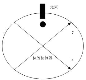
The invention discloses an automatic light beam capturing device, which comprises an optical antenna connected with an automatic tracking system. A Brewster window and a corner reflector are arranged on the emergent light side of the optical antenna. A focusing lens and a signal detector are arranged on the reflected light side of the Brewster window. A position-sensitive detector is arranged on the emergent light side of the Brewster window and is communicated with the automatic tracking system through a feedback channel. The light beam capturing method comprises that the optical antenna injects light signals to the corner reflector through the Brewster window after the optical antenna focuses the light signals; the corner reflector reflects the received light signals to the Brewster window, the reflected light is downward projected onto the position-sensitive detector, the Brewster window reflects partial light to the focusing lens and the light signals are received through the detector; and the position-sensitive detector calculates to obtain the position information of light, the position information is fed back to the automatic tracking system, and the automatic tracking system adjusts the transmitting direction and the pitch angle of the optical antenna. Since the invention combines an ATP with a signal laser, the invention has the advantages of simple structure, high economy and high feasibility and the device is suitable for ground atmosphere laser communication systems.

Description

technical field [0001] The invention belongs to the technical field of communication, and in particular relates to a light beam automatic capture device, and also relates to a method for using the device to capture light beams. Background technique [0002] In the space optical communication system, because the long-distance transmission of light will cause a large loss of light energy, the received light signal is often very weak. In addition, the background light (sun, moon, stars, etc.) will also produce strong interference, which greatly increases the difficulty of receiving optical signals. Therefore, how to capture, align and track light beams in the case of relatively long distances and strong background interference has become a key factor for the success of optical communication links. key. Ground atmospheric laser communication is different from space laser communication. In the space optical communication system, since the beam divergence angle of the communicati...

Claims


Application Information

Patent Timeline
Patent Type & Authority Applications(China)
IPC IPC(8): G02B27/30H04B10/00
Inventor 柯熙政卢宁赵黎
Owner XIAN UNIV OF TECH
Learn More