Fuel battery system

A fuel cell system and fuel cell technology, applied in fuel cells, fuel cell additives, solid electrolyte fuel cells, etc., can solve problems such as carbon precipitation, damage to single cells, and inability to operate stably

Inactive Publication Date: 2010-10-06
TOTO LTD
View PDF5 Cites 2 Cited by
  • Summary
  • Abstract
  • Description
  • Claims
  • Application Information

AI Technical Summary

Problems solved by technology

It is so difficult to accurately supply a small amount of water in the water supply pipe in a completely dry state, but if the inability to accurately supply water to the reformer is ignored, it may occur in the reformer

Method used


Image

  • Fuel battery system
  • Fuel battery system
  • Fuel battery system

Examples


Embodiment Construction

[0037] Hereinafter, embodiments of the present invention will be described with reference to the drawings. In order to facilitate understanding of the description, the same components are assigned the same reference numerals as much as possible in each drawing, and overlapping descriptions are omitted.

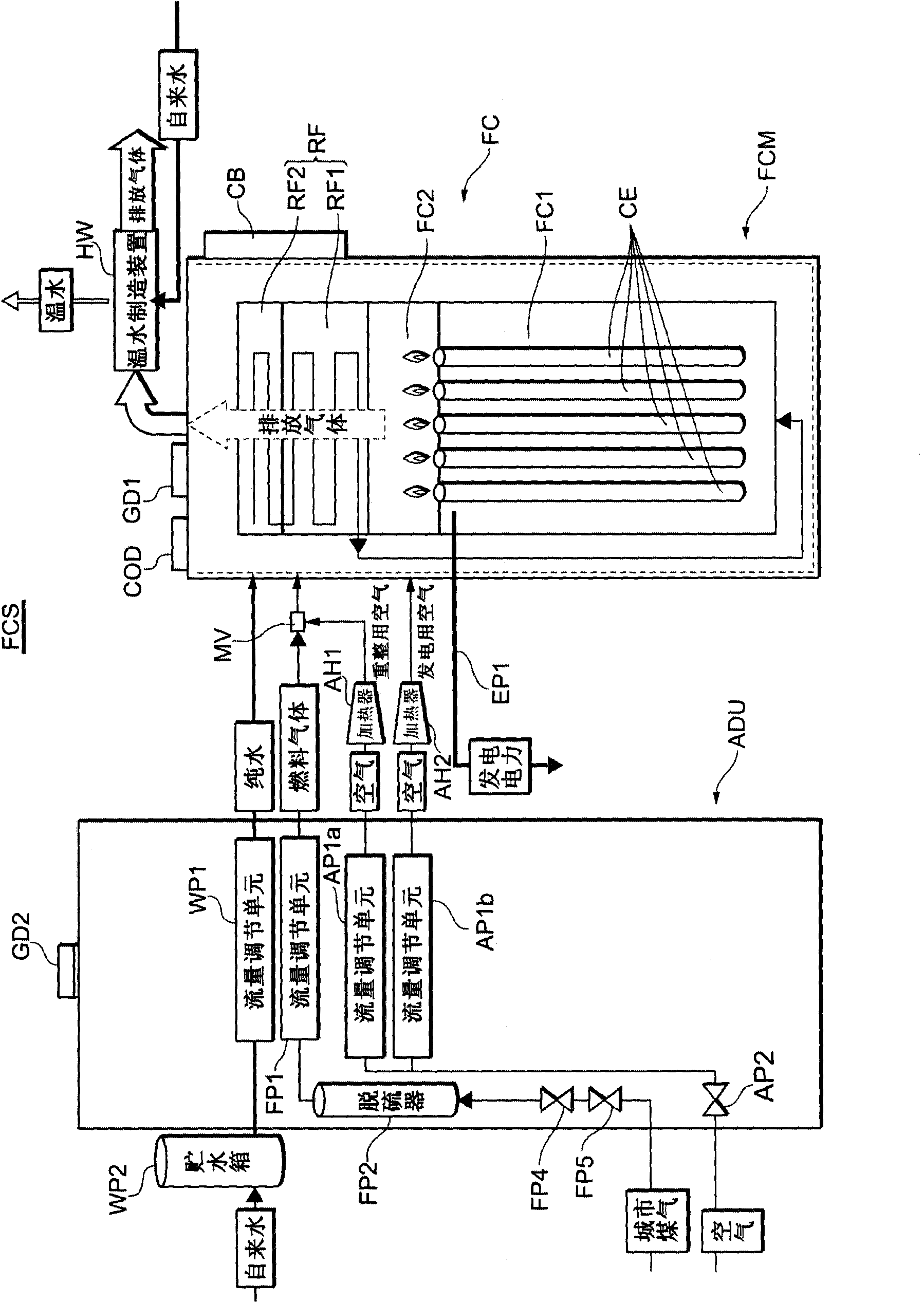
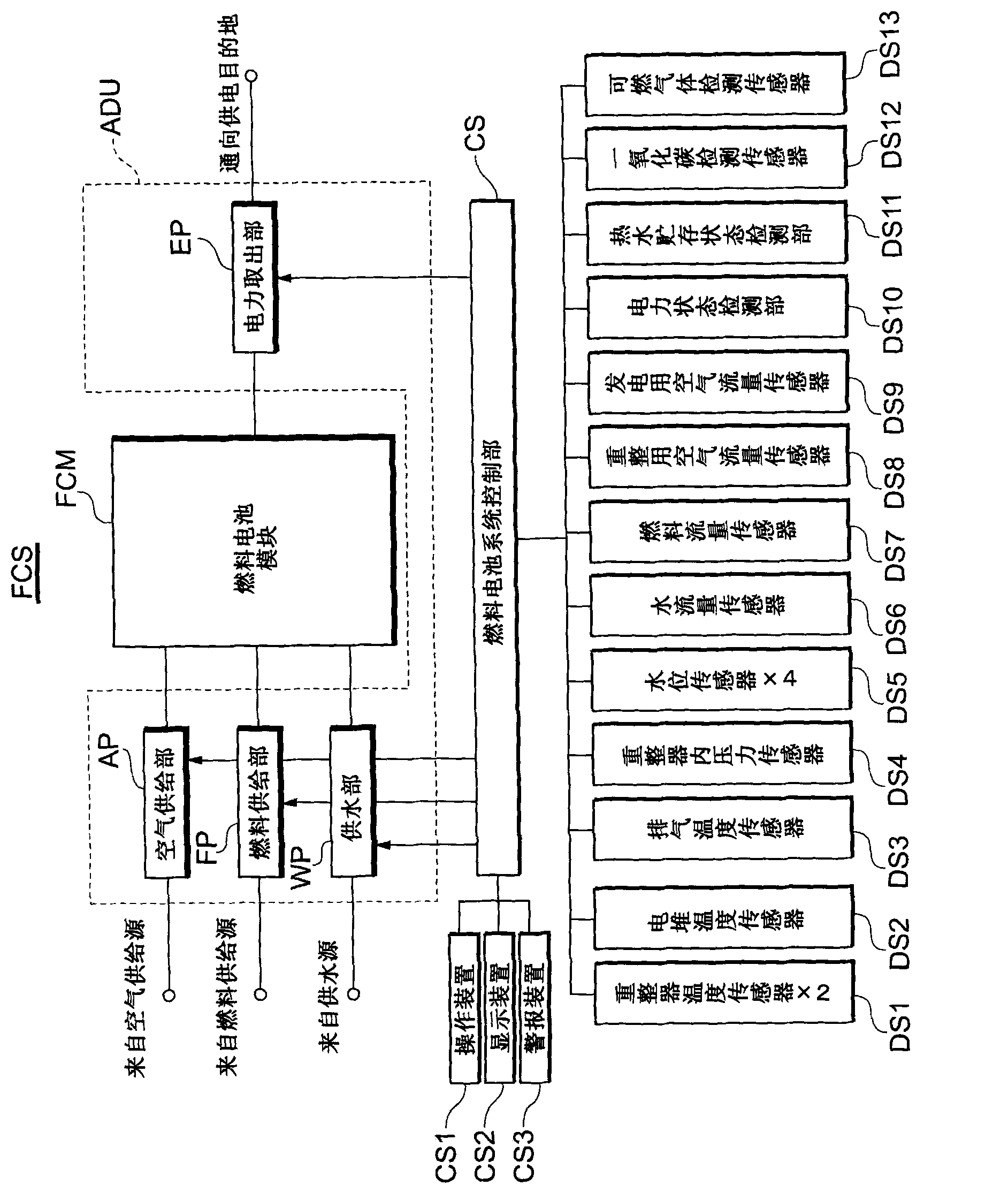
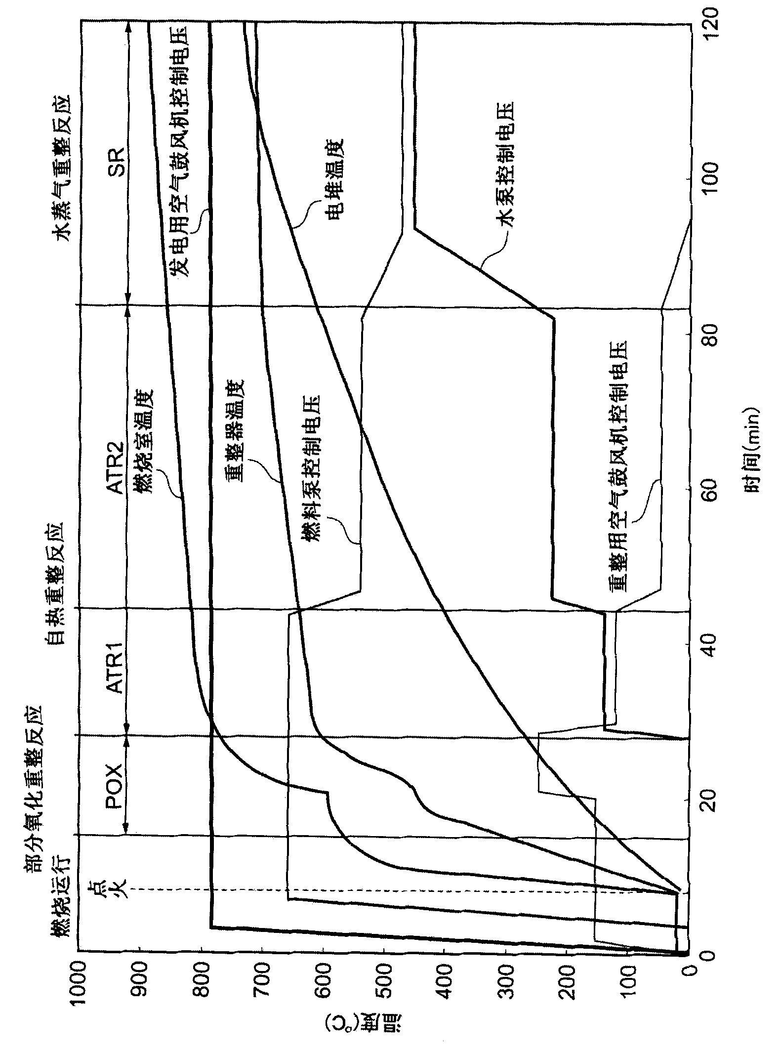
[0038] refer to figure 1 A fuel cell system according to one embodiment of the present invention will be described. figure 1 It is a schematic configuration diagram showing the overall configuration of a fuel cell system FCS as an embodiment. Such as figure 1 As shown, the fuel cell system FCS includes a fuel cell module FCM, an auxiliary equipment unit ADU, a water storage tank WP2, and a warm water manufacturing device HW.

[0039] First, the fuel cell module FCM will be described. The fuel cell module FCM includes a fuel cell FC, a reformer RF, a control box CB, a carbon monoxide detector COD, and a combustible gas detector GD1. The fuel cell FC is a solid electrolyte ...


PUM


Abstract

The invention provides a fuel cell system, which can accurately supply a small amount of water to a reformer and effectively operate continuously. Concretely, the fuel cell system (FCS) is characterized in that a water storage tank includes a first water storage tank (WP2a) which clamps a reverse osmosis membrane (20) and is equipped on an opposite side of a fuel cell module FCM (reformer) and a second water storage tank (WP2b) which is equipped on the fuel cell module FCM (reformer) side with respect to the reverse osmosis membrane (20). A pump includes a pump (111) which delivers water stored in the first water storage tank (WP2a) to the second water storage tank (WP2b) and a pulse pump (131) which delivers water stored in the second water storage tank (WP2b) to the fuel cell module FCM (reformer). The delivering capability of the pulse pump (131) is lower than that of the pump (111).

Description

technical field [0001] The present invention relates to a fuel cell system including solid electrolyte fuel cell (SOFC) cells. Background technique [0002] Conventionally, as such a fuel cell system, a solid electrolyte fuel cell (hereinafter also referred to as SOFC) unit cell is known as a bottomless or bottomed cylinder, etc. A fuel cell system in which the fuel gas of hydrogen is fed into an oxidant gas (air) on the opposite side to perform a power generation reaction. The fuel gas is a gas obtained by reforming a gas to be reformed such as city gas, and a so-called steam reforming reaction (hereinafter also referred to as SR) is carried out in a reformer for performing this reformation. A technique of supplying pure water to this reformer has been proposed (see, for example, Patent Document 1 below). [0003] Patent Document 1 below describes a technique for rapidly supplying pure water to a reformer. Furthermore, Patent Document 2 below describes a technique of sup...

Claims


Application Information

Patent Timeline
IPC IPC(8): H01M8/10H01M8/06H01M8/04
CPCY02E60/521Y02E60/525Y02E60/50
Inventor 中野清隆川村昌之大江俊春重住司土屋胜久
Owner TOTO LTD
Why Eureka
Try Eureka