Residential district night light environment detection system based on remote vehicle-mounted platform

A detection system and vehicle-mounted platform technology, applied in photometry, optical radiation measurement, motor vehicles, etc., can solve the problems of inaccurate measurement data, low detection efficiency, waste of manpower and material resources, etc., to achieve wide application prospects, easy to use and carry , the effect of improving the detection efficiency

Inactive Publication Date: 2010-10-13
TIANJIN UNIV
View PDF6 Cites 32 Cited by
  • Summary
  • Abstract
  • Description
  • Claims
  • Application Information

AI Technical Summary

Problems solved by technology

[0007] The utility model patent has the following problems: only one indicator of illuminance can be measured; and it must be measured point by point by the inspectors in the form of hand-held walking, which is intermittent sampling, and continuous data collection cannot be realized. The measurement position, measurement angle, and instrument stability and other indicators cannot be kept consistent; the measured data needs to be manually recorded by personnel, and after the recording is completed, manual computer data entry, storage and analysis are required
[0019] 1. The on-site measurement is carried out manually by the inspectors, item by item. Each person can only measure one indicator at a certain point

Method used


Image

  • Residential district night light environment detection system based on remote vehicle-mounted platform
  • Residential district night light environment detection system based on remote vehicle-mounted platform
  • Residential district night light environment detection system based on remote vehicle-mounted platform

Examples


Embodiment Construction

[0078] Below, describe in detail the present invention in conjunction with accompanying drawing

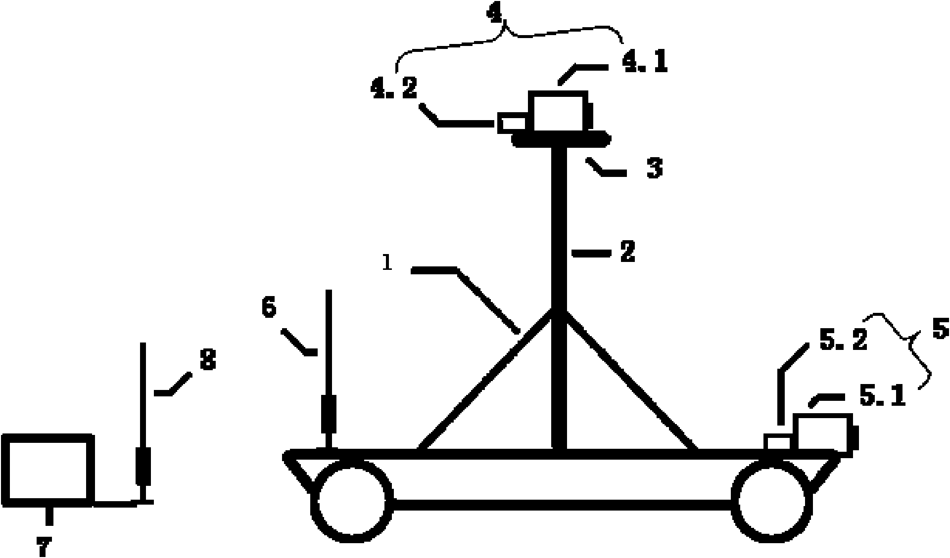
[0079] like figure 1 As shown, the residential area nighttime light environment detection system based on the remote control vehicle platform of the present invention includes a detection car 1, a lifting mechanism 2 arranged on the detection car 1, a rotating platform 3 arranged on the top of the lifting mechanism 2, installed on The image acquisition unit 4 on the rotating platform 3, the vehicle-mounted front-end operating condition acquisition unit 5 arranged at the front end of the detection vehicle 1, the vehicle-mounted control unit and the vehicle-mounted antenna 6 arranged on the detection vehicle 1, and the remote control computer unit 7 and the control antenna 8, wherein, the vehicle-mounted control unit receives the control signal sent by the remote control computer unit 7 through the vehicle-mounted antenna 6 and the control antenna 8 to control the parts as one respe...


PUM


Abstract

The invention relates to a residential district night light environment detection system based on a remote vehicle-mounted platform. The system comprises a lifting mechanism arranged on an inspection vehicle, a rotary tripod head arranged on the top of the lifting mechanism, an image acquisition unit arranged on the rotary tripod head, a vehicle-mounted front-end operational state acquisition unit arranged on the front end of the inspection vehicle, a vehicle-mounted control unit and vehicle-mounted antenna arranged on the inspection vehicle, a remote-control computer unit and a control antenna, wherein the vehicle-mounted control unit receives the control signals sent by the remote-control computer unit through the vehicle-mounted antenna and the control antenna and controls the devices respectively; the inspection vehicle realizes various movements; the lifting mechanism ascends or descends automatically; the rotary tripod head realizes free rotation; the image acquisition unit transmits image data to a remote computer; and the vehicle-mounted front-end operational state acquisition unit collects the illuminance near the ground continuously and instantly to transmit to the computer. The system of the invention can accurately and fast measure a plurality of detection indexes such as illuminance, brightness, chrominance and flare, realize remote-control measurement and avoid the threat of vehicles on roads to the security of human, because the light at night is dark.

Description

technical field [0001] The present invention relates to a nighttime light environment detection device, in particular to a nighttime light environment detection in a residential area based on a remote control vehicle-mounted platform that is fully computer-controlled, efficient and accurate, and can simultaneously detect multiple parameters of illuminance, brightness, chromaticity, and glare. system. Background technique [0002] With the development of my country's economic construction and the acceleration of urbanization, the construction of residential areas is in the ascendant, urban lighting has made great progress, and the lives of urban residents have also changed. Residents' outdoor activities at night have increased in content and time. This puts forward new requirements for the design of the nighttime light environment in the residential area and its surrounding areas: firstly, a good nighttime light environment in the residential area is one of the important com...

Claims


Application Information

Patent Timeline
IPC IPC(8): G01J1/00G01J3/46B62D57/02
Inventor 马剑党睿刘刚张明宇
Owner TIANJIN UNIV
Why Eureka
Try Eureka