Drive circuit for current drive element and drive method

A drive circuit, current drive technology, applied in instruments, static indicators, etc., can solve problems such as uneven brightness

Inactive Publication Date: 2010-10-13
AU OPTRONICS CORP
View PDF3 Cites 18 Cited by
  • Summary
  • Abstract
  • Description
  • Claims
  • Application Information

AI Technical Summary

Problems solved by technology

[0004] The purpose of the present invention is to provide a driving circuit suitable for driving current-driven elements, so as to improve the problem of uneven brightness caused by differences in the threshold voltages of transistors
[

Method used


Image

  • Drive circuit for current drive element and drive method
  • Drive circuit for current drive element and drive method
  • Drive circuit for current drive element and drive method

Examples


Embodiment Construction

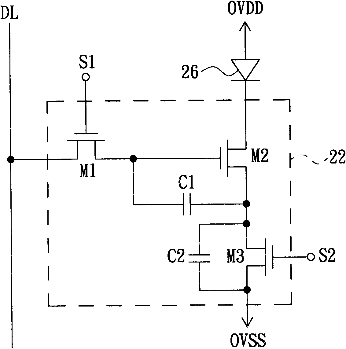
[0034] see figure 2 , which shows the electrical connection relationship between a driving circuit and an organic light emitting diode related to an embodiment of the present invention. Such as figure 2 As shown, the driving circuit 22 is suitable for a current driving device such as an OLED 26, which is a three-transistor-two-capacitor (3T2C) architecture. The driving circuit 22 includes transistors M1 , M2 and M3 and capacitors C1 and C2 , and each of the transistors M1 , M2 and M3 are N-type transistors. In this embodiment, the transistors M1, M2, and M3 are all used as switches, and the gate, drain, and source of each transistor M1, M2, and M3 are respectively the control end, the first access end, and the second access end of the switch. and the transistors M1, M2, and M3 constitute a switch module for determining whether to allow current to flow through the organic light emitting diode 26.

[0035]Specifically, the gate of the N-type transistor M1 is electrically co...


PUM


Abstract

The invention relates to a drive circuit for driving a current drive element with a first end and a second end, wherein the first end of the current drive element is electrically coupled to a first preset potential. The drive circuit comprises a switch module, a first capacitor and a second capacitor, wherein the switch module is electrically coupled to a data line, the second end of the current drive element and a second preset potential and used for determining whether to allow the current to pass through the current drive element; the first end and the second end of the first capacitor are respectively electrically coupled to different nodes in the switch module, and the first end of the first capacitor receives the potential on the data line in the specific time period due to the electrical coupling relation; the first end of the second capacitor is electrically connected with the second end of the first capacitor; and the second end of the second capacitor is electrically coupled to the second preset potential. The invention also provides a drive method applicable to the drive circuit.

Description

technical field [0001] The present invention relates to the field of display technology, and in particular to a driving circuit and a driving method suitable for driving current-driven elements. Background technique [0002] The pixel of an Organic Light Emitting Diode (OLED) display generally uses transistors and storage capacitors to store charges to control the brightness of the OLED. Different magnitudes of current produce different degrees of bright light. See figure 1 , which is a schematic diagram of a conventional pixel circuit. The pixel circuit 10 includes a driving circuit 12 and an organic light emitting diode 16; the driving circuit 12 is used to control the brightness performance of the organic light emitting diode 16, and has a two-transistor-one-capacitor (2T1C) structure. Specifically, the drive circuit 12 includes an N-type transistor M1, a P-type transistor M2, and a capacitor C1; the drain of the N-type transistor M1 is electrically coupled to the data...

Claims


Application Information

Patent Timeline
IPC IPC(8): G09G3/32G09G3/3208
Inventor 周佳伶
Owner AU OPTRONICS CORP
Why Eureka
Try Eureka