Method for dynamically adjusting busbar voltage to improve grid connection efficiency

A bus voltage, dynamic adjustment technology, applied in the direction of single network parallel feeding arrangement, etc., can solve the problems of increasing the bus support capacitor stress, reducing the service life of the capacitor, increasing the stress of the booster circuit components, etc., to improve the efficiency and reliability of the whole machine performance, prolong service life, and reduce device stress

Active Publication Date: 2010-10-13
SUNGROW POWER SUPPLY CO LTD
View PDF5 Cites 13 Cited by
  • Summary
  • Abstract
  • Description
  • Claims
  • Application Information

AI Technical Summary

Problems solved by technology

[0004] 1) When the input DC voltage of the grid-connected inverter is less than 300V, the bus voltage is boosted to 400V through the boost circuit of the previous stage. Compared with boosting to 300V, the duty cycle of the boost circuit is much larger. Not only reduces the efficiency of the boost circuit, but also increases the stress of the boost circuit components;
[0005] 2) When the input DC voltage of the grid-connected inverter is between 300V and 400V, if the bus voltage is to be controlled to 400V, the boost circuit must still work, which not only reduces the system efficiency, but also increases the number of switching operations, making Reduced system lifetime and reliability
[0006] 3) The control bus voltage has been at a higher voltage, which increases the stress of the bus support capacitor and reduces the service life of the capacitor;
[0007] 4) The control bus voltage has been at a higher voltage, which increases the stress on the inverter circuit components and reduces the inverter efficiency

Method used


Image

  • Method for dynamically adjusting busbar voltage to improve grid connection efficiency
  • Method for dynamically adjusting busbar voltage to improve grid connection efficiency
  • Method for dynamically adjusting busbar voltage to improve grid connection efficiency

Examples


Embodiment 1

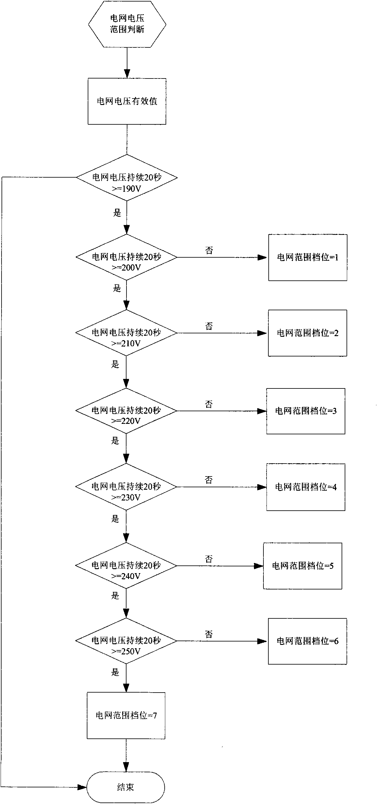
[0024] see figure 1 shown. The minimum and maximum grid voltage has a working range of about 70V. In order not to adjust the bus voltage too frequently, the control system divides the range of 70V into 7 gears, each 10V is a gear. In the first step, the control system first needs to judge the current grid gear. The control system detects the effective value of the grid voltage in real time. When the effective value of the grid voltage is greater than 190V but less than 200V for 20 seconds, the grid gear is considered to be equal to 1. In actual operation, the instantaneous fluctuation of the power grid is very frequent, so when judging the voltage level of the power grid, only when the power grid remains in a certain range for 20 seconds, can it be judged to switch to this level. When the effective value of the grid voltage is greater than 200V but less than 210V and lasts for 20 seconds, the grid gear is considered to be equal to gear 2; when the effective value of the grid...

Embodiment 2

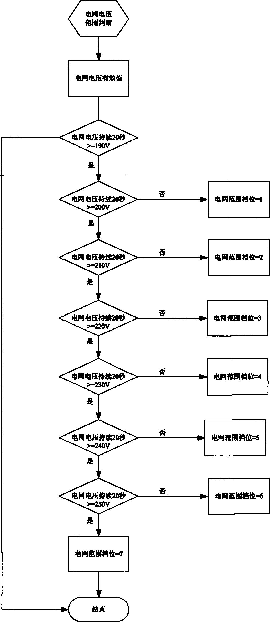
[0026] The minimum and maximum grid voltage has a working range of about 70V. In order not to adjust the bus voltage too frequently, the control system divides the range of 70V into 7 gears, each 10V is a gear. In the first step, the control system first needs to judge the current power grid gear. The control system detects the effective value of the grid voltage in real time. When the effective value of the grid voltage is greater than 190V but less than 200V, it is considered that the power grid gear is equal to gear 1, and other gears Judgments are made in this way. All the other are with embodiment 1.

Embodiment 3

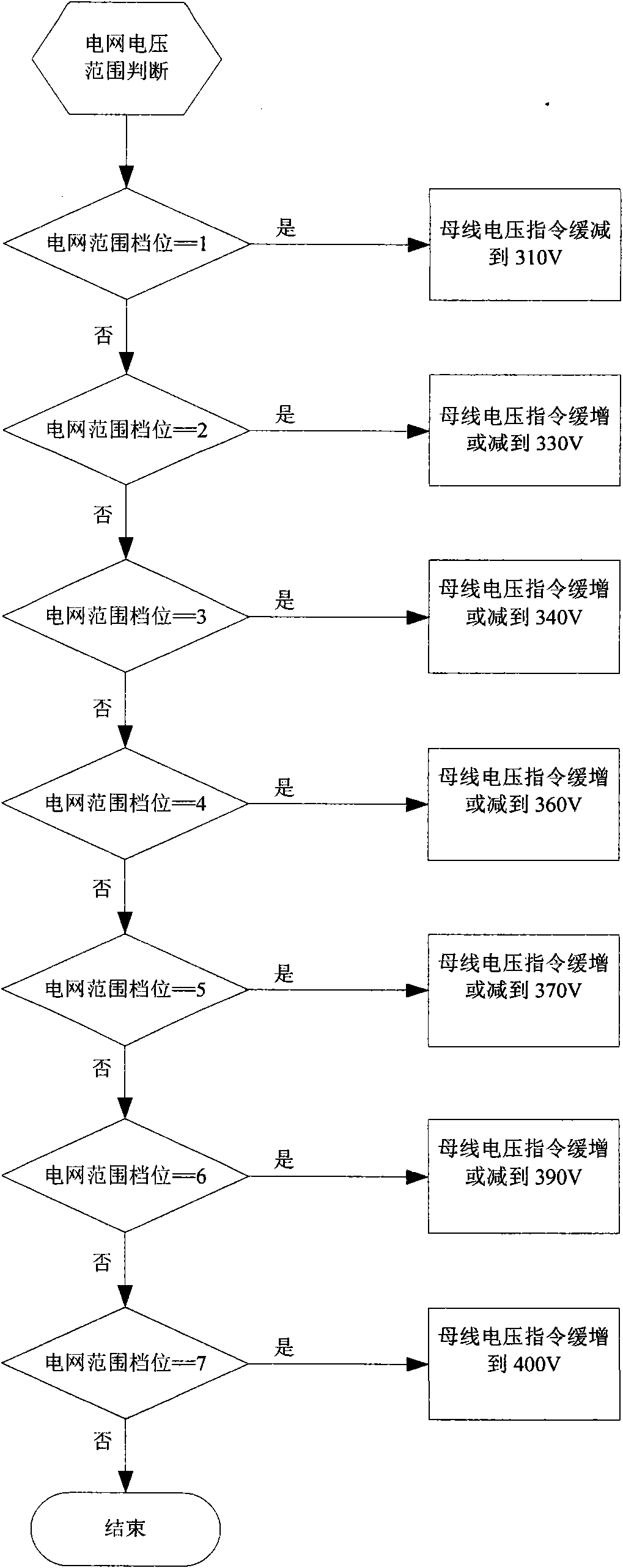
[0028] The minimum and maximum grid voltage has a working range of about 70V. In order not to adjust the bus voltage too frequently, the control system divides the range of 70V into 7 gears, each 10V is a gear. In the first step, the control system first needs to judge the current power grid gear. The control system detects the effective value of the grid voltage in real time. When the effective value of the grid voltage is greater than 190V but less than 200V, it is considered that the power grid gear is equal to gear 1, and other gears Judgments are made in this way. Then determine the size of the bus voltage command according to the gear of the grid voltage, such as figure 2 Shown: when the power grid gear is gear 1, the bus voltage command at this time is not equal to 310V, then it is set to 310V; the rest is the same as in embodiment 1.


PUM


Abstract

The invention relates to a method for dynamically adjusting busbar voltage to improve grid connection efficiency. The working range of grid voltage from lowest limit to highest limit is divided into at least two levels and each level corresponds to a set busbar voltage directive value; and a control system detects the effective value of the grid voltage in real time, and when the grid voltage is within one level, if the busbar voltage directive value at the moment is not equal to the set busbar voltage directive value corresponding to the level, the busbar voltage directive value is adjusted to the set value. Since the amplitude of the busbar voltage is dynamically adjusted according to the grid voltage value detected in real time, the invention has the advantages that the overall efficiency and the reliability of the grid-connected inverter are improved, the device stress is reduced and the service life of the capacitor is prolonged.

Description

technical field [0001] The invention relates to a control method of a grid-connected inverter, in particular to a method for dynamically adjusting bus voltage to improve grid-connected efficiency. Background technique [0002] The basic condition for the grid-connected operation of the grid-connected inverter is: the amplitude of the bus voltage is not less than the peak value of the grid voltage. For grid-connected inverters with a multi-stage conversion topology, especially the grid-connected inverters in which the front stage is a booster circuit, the middle is a bus support capacitor, and the rear stage is an inverter circuit, the DC input of the grid-connected inverter After the voltage is transformed by the booster circuit, the output bus voltage meets the basic conditions for grid-connected operation. At present, the method of stably controlling the bus voltage at a fixed voltage value is usually adopted. [0003] Generally, grid-connected inverters are required to ...

Claims


Application Information

Patent Timeline
Patent Type & Authority Applications(China)
IPC IPC(8): H02J3/38
Inventor 曹仁贤倪华梅晓东赵为
Owner SUNGROW POWER SUPPLY CO LTD
Why Eureka
Try Eureka