Winding device and winding method of motor armature of electric motor vehicle

An armature winding and winding method technology, applied in the field of motor rotor winding assembly process, can solve the problems of high production cost, high labor intensity, large space size, etc., and achieve convenient winding, labor saving, and winding efficiency. high effect

Inactive Publication Date: 2010-10-13
崔建伟
View PDF0 Cites 7 Cited by
  • Summary
  • Abstract
  • Description
  • Claims
  • Application Information

AI Technical Summary

Problems solved by technology

In actual production, there are indeed situations that cannot meet one of the above three conditions, such as electric bicycle motors, each magnetic shoe of this motor is wound with a coil, and each coil is wound by multiple strands of enameled wire , the size of the notch is very small, only about 2 mm. Due to the large space occupied by multi-strand wires, and the problem of "twist twist" when winding, it is impossible to use the direct winding method.
The

Method used


Image

  • Winding device and winding method of motor armature of electric motor vehicle
  • Winding device and winding method of motor armature of electric motor vehicle
  • Winding device and winding method of motor armature of electric motor vehicle

Examples


Example Embodiment

[0022] Example 1:

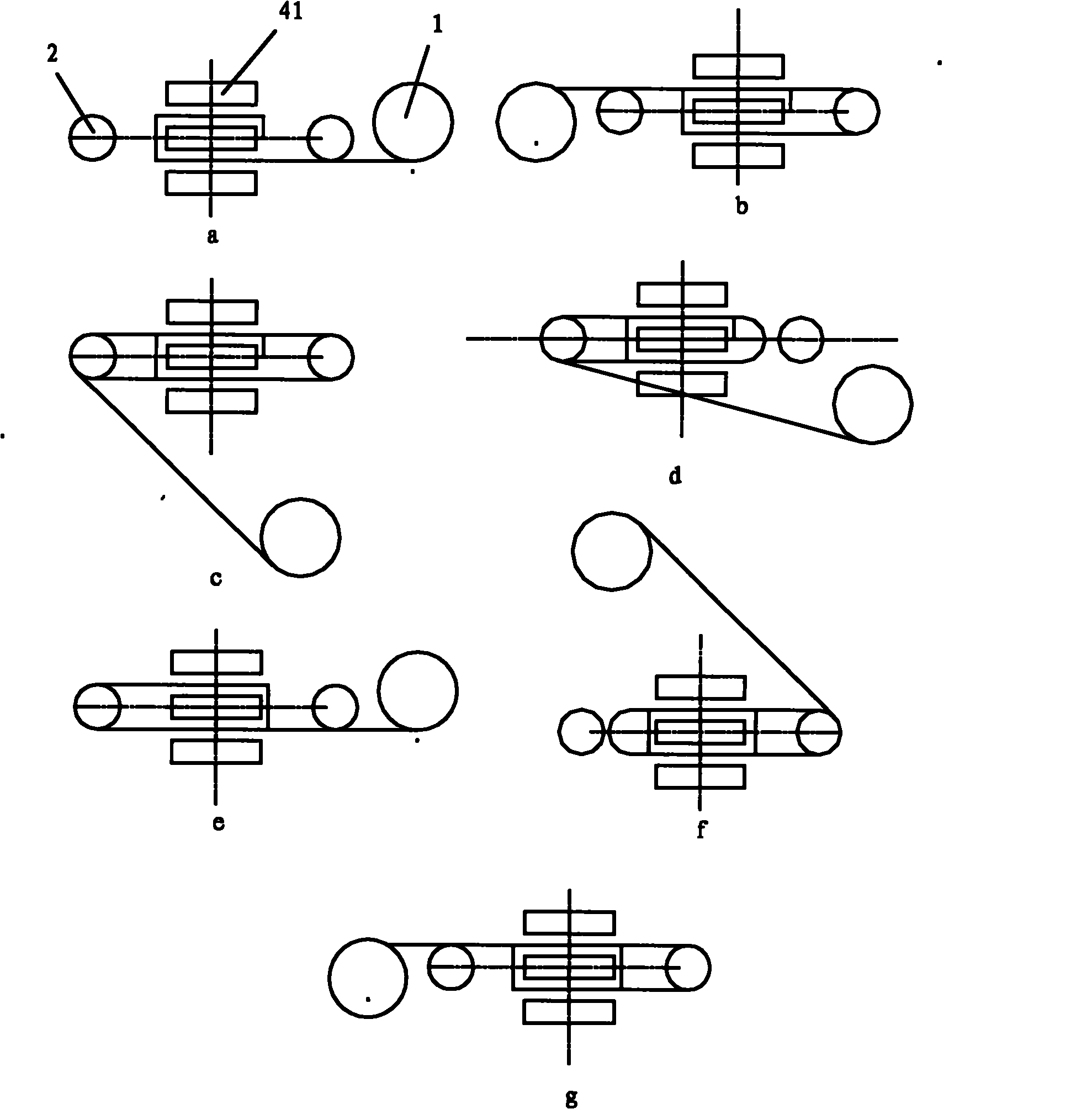
[0023] exist figure 2 In the process, manually align the wires on the wire reel with the first slot, and the number of wire strands on the wire reel has been coiled according to the design, then manually pull out the wires, and assemble the first coil of wires of the first winding on the magnetic shoe 41 on, fasten. Start the machine and start winding automatically. When the reel rotates 180 degrees to figure 2 -b position, at this time there is a half-turn wire wound on the right swing bar, and the coil is formed by figure 2 -b to figure 2 -c revolves about 120 degrees. During this process, the right crimping sleeve 7 presses a half-turn coil into the wire groove, and the reel continues to revolve. The right crimping block is figure 2 The -d position is raised, and the right swing lever starts to rotate clockwise, so that the wire wound on the right swing lever is released; the reel continues to revolve until figure 2 -e position, and the wire ...

Example Embodiment

[0024] Example 2

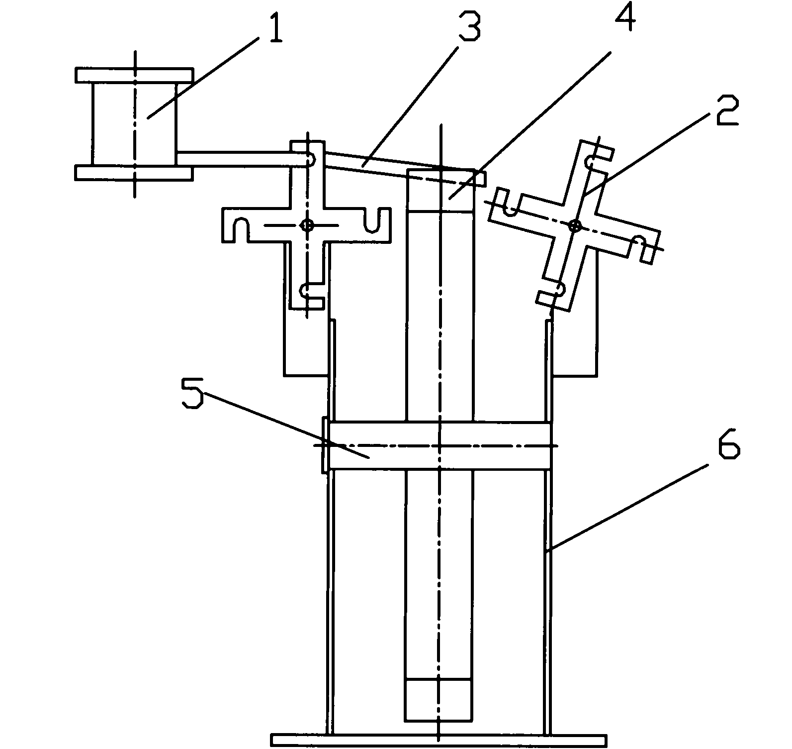
[0025] image 3 It is another embodiment based on the above principles. Compared with embodiment 1, the left and right crimping sleeves are omitted in embodiment 2, but there are hook-shaped notches on the left and right swing bars. When the wire reel rotates, wrap the wire around the notch of the cross pendulum. Rely on the rotation of the fork to send the wire into the wire slot. Referring to Example 1 figure 2 , this winding method is: in figure 2 In -a position, manually align the wire reel with the first slot, the number of wire strands on the wire reel has been coiled according to the design, manually pull out the wire, and assemble the first coil of the first coil of the winding on the magnetic shoe Put it on, tie it firmly, start the machine, and start winding automatically. The reel rotates 180 degrees to figure 2 In the position of -b, there is a half-turn wire wound around the right swing bar. reel by figure 2 -b to figure 2 -c revo...


PUM


Abstract

The invention discloses a winding device and a winding method of a motor armature of an electric motor vehicle. The winding device comprises a winding stand, a wire coil and an iron core fixed shaft which are arranged on the wire coil, the wire coil rotates around a winding shaft of the stand; two winding suspension mechanisms are respectively arranged on two sides of the stand; each winding suspension mechanism comprises a suspension part and a power component which is connected with the suspension part to control the suspension part to rotate; and each suspension part is provided with two stations, i.e. a first station for the upper end of the suspension part positioned in a paying-off plane of the wire coil to wind the winding and a second station for the upper end of the suspending mechanism of the winding to swing to the inner side of the stand and release the winding. Compared with the prior art, in the method, the winding to be wound is firstly wound on the suspension part of the suspending mechanism, the suspension part is swung by swinging the suspending mechanism to release the winding on the suspension part from the suspension part, the winding can be automatically furled into a wire trough under the action of the tension of the wire coil, the winding is convenient and fully automatic, the labor force is saved and the winding efficiency is high.

Description

technical field [0001] The invention is an assembly process of motor rotor winding, which combines the characteristics of direct winding method and indirect winding method, and is especially suitable for the situation that each winding contains multiple strands of enameled wire, and the notch is small and the number of crossing slots is small. Background technique [0002] There are two current motor rotor winding processes. One is the direct winding method, which uses some kind of machinery to directly wind the single-strand enameled wire in the slot of the rotor. Typical winding equipment is such as a flying fork winding machine; the other is the indirect winding method. The machine winds the enameled wire into a coil with the required number of turns, and then uses the wire embedding machine to embed the winding into the wire slot. [0003] These two processes have been widely used in production practice, but they are required to meet four conditions at the same time: si...

Claims


Application Information

Patent Timeline
IPC IPC(8): H02K15/09
CPCY02T10/641Y02T10/64
Inventor 崔建伟
Owner 崔建伟
Why Eureka
Try Eureka