Outer rotor permanent magnetic synchronous motor

A technology of permanent magnet synchronous motor and external rotor, which is applied in the direction of synchronous motor with stationary armature and rotating magnet, magnetic circuit rotating parts, magnetic circuit shape/style/structure, etc., which can solve the time-consuming and installation process of motor cumbersome and other problems, to achieve the effect of improving processing efficiency, simple structure and high running stability

Inactive Publication Date: 2010-10-13
HARBIN INST OF TECH
View PDF8 Cites 4 Cited by
  • Summary
  • Abstract
  • Description
  • Claims
  • Application Information

AI Technical Summary

Problems solved by technology

[0007] The purpose of the present invention is to solve the problem that in the existing permanent magnet synchronous motor with outer rotor structure, the permanent magnet is positioned and installed thr

Method used


Image

  • Outer rotor permanent magnetic synchronous motor
  • Outer rotor permanent magnetic synchronous motor
  • Outer rotor permanent magnetic synchronous motor

Examples


specific Embodiment approach 1

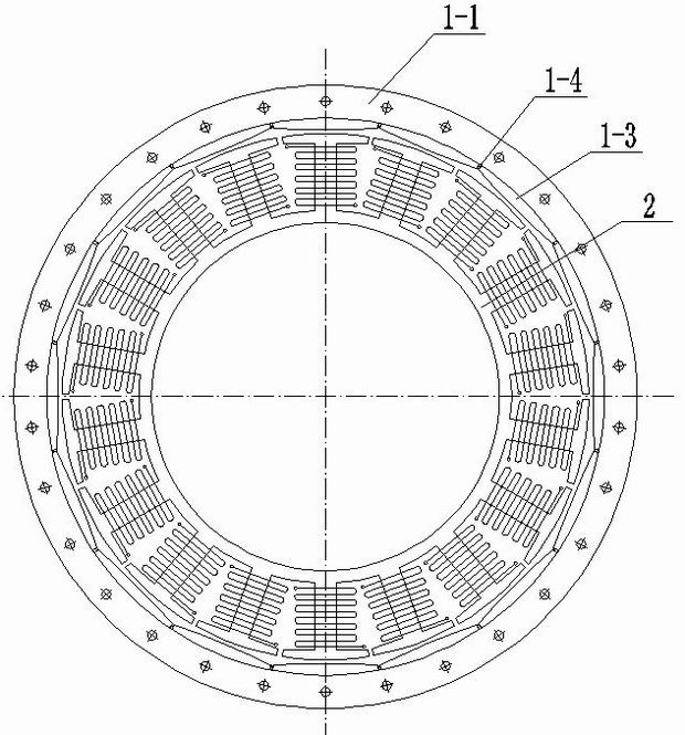
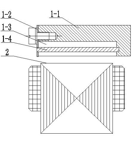
[0011] Specific implementation mode one: the following combination Figure 1 to Figure 4 Describe this embodiment, this embodiment comprises stator 2 and rotor, and it adopts the structure that stator 2 is inside, and rotor is outside, and the outer ring surface of described stator 2 and the inner ring surface of rotor are air gaps, and rotor is formed by rotor yoke 1-1, composed of rotor pressing plate 1-2, permanent magnet 1-3 and key 1-4, rotor yoke 1-1 and rotor pressing plate 1-2 are fixed together to form an inner ring surface with a groove, the groove A plurality of keys 1-4 arranged in the axial direction are equally divided into a plurality of accommodating spaces, and a permanent magnet 1-3 is respectively embedded in each accommodating space.

[0012] In this embodiment, the permanent magnets 1-3 are embedded in multiple accommodating spaces formed by the keys 1-4, which can improve the inaccurate bonding and positioning of the permanent magnets 1-3 and the insuffic...

specific Embodiment approach 2

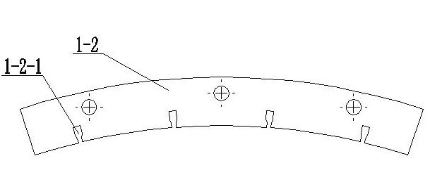
[0014] Embodiment 2: The difference between this embodiment and Embodiment 1 is that a plurality of trapezoidal grooves 1-2-1 are provided on the inner ring side of the rotor pressure plate 1-2, and each trapezoidal groove 1-2-1 Secure one end of a key 1-4. Other components and connections are the same as those in Embodiment 1.

[0015] The function of key 1-4 is to separate the placement space of multiple permanent magnets 1-3, and the setting of trapezoidal groove 1-2-1 is to ensure that key 1-4 will not move in the radial direction, better Secure the keys 1-4, thereby securing the permanent magnets 1-3.

specific Embodiment approach 3

[0016] Embodiment 3: The difference between this embodiment and Embodiment 1 or 2 is that the rotor pressing plate 1-2 is integrated or spliced. Other compositions and connections are the same as those in the first or second embodiment.

[0017] The rotor press plate 1-2 of the one-piece structure has higher processing and installation accuracy, but when the outer diameter of the motor is larger, the outer diameter of the rotor press plate 1-2 will also be larger, which makes it more difficult to process and will result in more machining. waste, so it is suitable for occasions where the outer diameter of the motor is small; the rotor pressure plate 1-2 of the spliced ​​structure is formed by splicing multiple fan-shaped plates to form a ring. Compared with the integrated structure, the processing and installation accuracy is slightly lower, but the processing Easy, less processing waste, suitable for occasions with large motor outer diameters.


PUM


Abstract

The invention relates to an outer rotor permanent magnetic synchronous motor, belonging to the technical field of motors, and solves the problems that in the current permanent magnetic synchronous motor with the outer rotor structure, a permanent magnet is positioned and installed through a magnetic pole positioning sleeve, so that the installation process is complex and the processing of the motor is time-consuming. The outer rotor permanent magnetic synchronous motor comprises a stator and a rotor and adopts a structure that the stator is inside and the rotor is outside, wherein an air gap is formed between the outer ring surface of the stator and the inner ring surface of the rotor; the rotor is composed of a rotor yoke, a rotor press plate, permanent magnets and keys; the rotor yoke and the rotor press plate are fixed together to form an inner circular ring surface with a groove; the groove is evenly divided into a plurality of containing spaces by a plurality of axially set keys; and one permanent magnet is respectively embedded in each containing space. The invention is used as a permanent magnetic synchronous motor.

Description

technical field [0001] The invention relates to an outer rotor permanent magnet synchronous motor, belonging to the technical field of motors. Background technique [0002] Permanent magnet synchronous motors and their servo systems are widely used in industrial drive and servo control fields due to their small size, high efficiency, and good dynamic response characteristics. From the perspective of motor structure, permanent magnet synchronous motors can be divided into two types: inner rotor structure and outer rotor structure. Compared with the inner rotor structure, the permanent magnet synchronous motor with the outer rotor structure has the following advantages: [0003] Under the condition of the same volume, the permanent magnet synchronous motor with the outer rotor structure generates a larger torque; [0004] The permanent magnet synchronous motor with outer rotor structure has a large moment of inertia, so the motor runs smoothly and is easy to overcome the inf...

Claims


Application Information

Patent Timeline
IPC IPC(8): H02K21/22H02K1/27H02K1/28
Inventor 邹继斌王骞徐永向胡建辉李勇尚静刘承军
Owner HARBIN INST OF TECH
Why Eureka
Try Eureka