Barrel-type electromagnetic speed regulation system

An electromagnetic speed regulation and cylinder type technology, which is applied in the direction of control system, electrical components, control electromechanical brake, etc., can solve the problems of increased design difficulty, limited speed regulation range, small size of magnet, etc., to reduce demagnetization phenomenon and reduce circuit magnetism Resistance, improve the effect of transmission torque

Inactive Publication Date: 2010-10-13
ANSHAN QINYUAN ENERGY SAVING EQUIP MFG
View PDF5 Cites 8 Cited by
  • Summary
  • Abstract
  • Description
  • Claims
  • Application Information

AI Technical Summary

Problems solved by technology

The disadvantages of this type of magnetic coupling system are: the magnet is small in size, the torque generated is small, and the speed regulation range is limited; the structure is complex, which increases the difficulty of design; it is easy to cause demagnetization

Method used


Image

  • Barrel-type electromagnetic speed regulation system
  • Barrel-type electromagnetic speed regulation system
  • Barrel-type electromagnetic speed regulation system

Examples


Embodiment Construction

[0015] The specific embodiments of the present invention will be further described below in conjunction with the accompanying drawings:

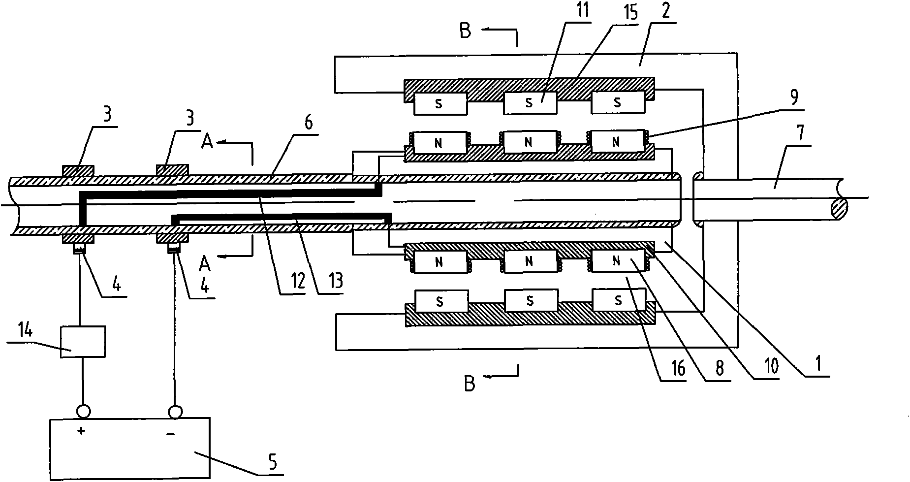
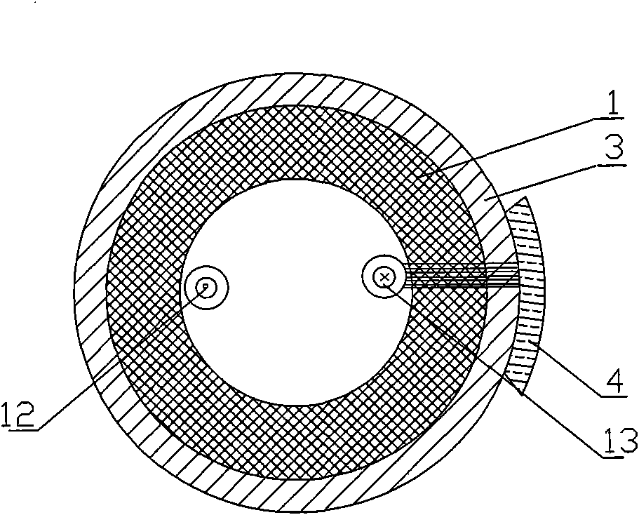
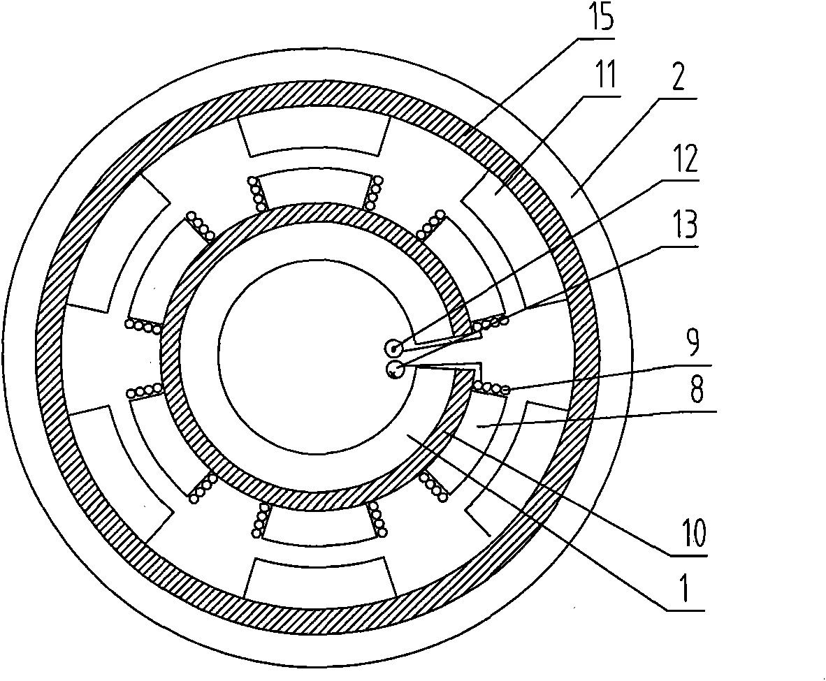
[0016] See figure 1 , figure 2 , a cylindrical electromagnetic speed control system, including an inner drum rotor 1, an outer drum rotor 2, a conductive slip ring 3, a brush 4, a DC power supply 5, the inner drum rotor 1 is arranged at the end of the input shaft 6, and the input shaft 6 is hollow Structure, the outer cylinder rotor 2 is arranged at the end of the output shaft 7, the inner cylinder rotor 1 is coaxially nested with the outer cylinder rotor 2, the inner cylinder rotor 1 is provided with a soft magnet 8, the soft magnet 8 is provided with a coil 9, There is also an iron lining 10 between the magnet 8 and the inner cylinder rotor 1, and a permanent magnet 11 is provided on the outer cylinder rotor 2 at the position corresponding to the soft magnet 8. There is a certain air gap 16 between the soft magnet 8 and the permanent mag...


PUM


Abstract

The invention relates to a barrel-type electromagnetic speed regulation system, which comprises an inner barrel rotor, an outer barrel rotor, conductive slip rings, electric brushes and a DC power supply, wherein the inner barrel rotor is arranged at an input shaft end; the outer barrel rotor is arranged at an output shaft end; the inner barrel rotor and the outer barrel rotor are coaxially nested; the inner barrel rotor is provided with soft magnets of which each is provided with a coil; positions, corresponding to the soft magnets, on the outer barrel rotor are provided with permanent magnets; the input shaft is provided with the conductive slip rings which are matched with the electric brushes; the electric brushes are connected with the anode and the cathode of the DC power supply; the conductive slip rings are connected with the coils by lead wires; and the coils wound by the circumferentially adjacent soft magnets arranged on the inner barrel rotor rotate in opposite directions, while the coils wound by the axially adjacent soft magnets are in the same direction. The barrel-type electromagnetic speed regulation system has the advantages that: the soft magnets on the inner barrel rotor reduce demagnetization and realize control over a rotation speed of the output shaft; and the barrel structure can generate strong electromagnetism, and the areas of the permanent magnets are great, so working efficiency is improved.

Description

technical field [0001] The invention relates to the field of industrial control, in particular to a cylindrical electromagnetic speed regulating system. Background technique [0002] At present, variable frequency speed regulation is widely used in industrial sites. The output speed of the motor is controlled by controlling the input frequency of the motor. The price is relatively expensive, and the structure and operation are complicated. It affects communication and has high requirements on the environment, so it is not suitable for working in harsh environments. With the development of science and technology, the permanent magnet coupling speed control system came into being. It changes the output torque by adjusting the air gap between the permanent magnet and the copper disc, so as to achieve the purpose of speed regulation. The defects of this type of magnetic coupling system are: the magnet is small in size, the torque generated is small, and the speed regulation ra...

Claims


Application Information

Patent Timeline
Patent Type & Authority Applications(China)
IPC IPC(8): H02P15/00
Inventor 王大志马忠威崔箫王旭江宁周伟仑
Owner ANSHAN QINYUAN ENERGY SAVING EQUIP MFG
Why Eureka
Try Eureka