Closed-loop driving circuit for micromechanical resonance structure

A technology of resonant structure and driving circuit, applied in the direction of electrical components, impedance network, etc., can solve the problems of unstable resonance of resonant structure, difficult debugging, small dynamic range of circuit signal, etc., to avoid coupling influence, facilitate debugging, and expand linearity. The effect of the working area

Inactive Publication Date: 2010-10-13
江苏巨邦环境工程集团股份有限公司 +1
View PDF2 Cites 30 Cited by
  • Summary
  • Abstract
  • Description
  • Claims
  • Application Information

AI Technical Summary

Problems solved by technology

[0005] The purpose of the present invention is: in order to overcome the mutual coupling influence of gain adjustment and phase adjustment in the debugging process of the closed-loop drive circuit in the prior art, it is difficult to debug; the dynamic range of the circuit signal is small, and the shortcoming of the closed-loop

Method used


Image

  • Closed-loop driving circuit for micromechanical resonance structure
  • Closed-loop driving circuit for micromechanical resonance structure
  • Closed-loop driving circuit for micromechanical resonance structure

Examples


Embodiment 1

[0025] The first type of closed-loop drive circuit for a micromechanical resonant structure. The specific structure corresponding to the micromechanical resonant structure 4 in this embodiment is Figure 6 The shown comb-driven micromechanical resonant structure with the stationary teeth disconnected, Figure 8 The structure is abstracted as a micromechanical resonant structure-14, and its specific implementation is as follows:

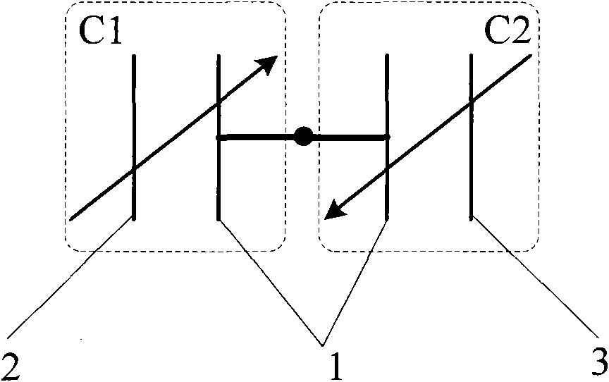
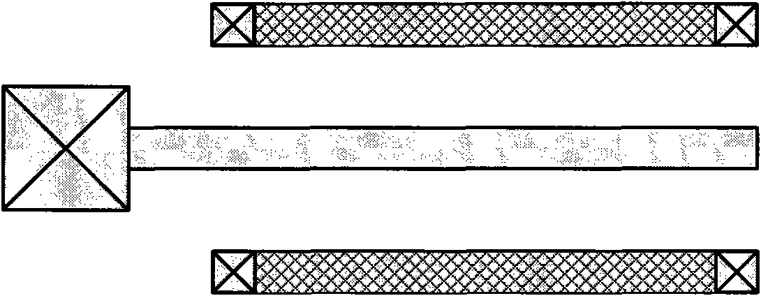
[0026] refer to Figure 8 , the present embodiment is directed to a micromechanical resonant structure 14, which belongs to a structure in which the fixed electrodes on both sides of the common electrode 1 are disconnected. The micromechanical resonant structure 14, corresponding to figure 1 In the electrical model shown, the fixed electrode I2 is disconnected into two electrodes, the sensitive electrode AI15 and the driving electrode AI17; the fixed electrode II3 is disconnected into two electrodes, the sensitive electrode AII16 and the driving ele...

Embodiment 2

[0031] The second type of closed-loop drive circuit for micromechanical resonant structures. The specific structure corresponding to the micromechanical resonant structure 4 in this embodiment is Figure 6 The comb-driven micromechanical resonant structure with the stationary teeth disconnected is shown, Figure 9 The structure is abstracted as a micromechanical resonant structure-14, and its specific implementation is as follows:

[0032] refer to Figure 9 , the present embodiment is directed to a micromechanical resonant structure 14, which belongs to a structure in which the fixed electrodes on both sides of the common electrode 1 are disconnected. The micromechanical resonant structure 14, corresponding to figure 1 In the electrical model shown, the fixed electrode I2 is disconnected into two electrodes, the sensitive electrode AI15 and the driving electrode AI17; the fixed electrode II3 is disconnected into two electrodes, the sensitive electrode AII16 and the driving ...

Embodiment 3

[0036] The third type of closed-loop drive circuit for micromechanical resonant structures. The specific structure corresponding to the micromechanical resonant structure 4 in this embodiment can be Figure 2 to Figure 5 Either structure shown, Figure 10 The structure is abstracted as a micromechanical resonant structure 227, and its specific implementation is as follows:

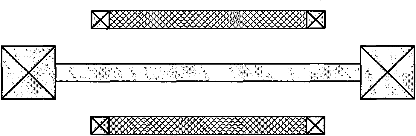
[0037] refer to Figure 10 , this implementation is aimed at the micromechanical resonant structure 27, which belongs to the structure in which the fixed electrodes on both sides of the common electrode are connected. The MEMS resonant structure II 27, corresponds to figure 1 In the electrical model shown, the fixed electrode I2 is integrated, and the fixed electrode II3 is also integrated. In this embodiment, the fixed electrode I2 and the fixed electrode II3 are embodied as a sensitive electrode B24 and a driving electrode B25 respectively.

[0038] First, the common electrode 1 of the second microme...


PUM


Abstract

The invention discloses a closed-loop driving circuit for a micromechanical resonance structure, which is an alternating-current automatic gain control closed-loop self-excited driving circuit mainly comprising an amplitude limiting circuit 7, a band-pass filter 8, an automatic gain control loop 9 and a phase compensating circuit 12. The automatic gain control loop 9 adjusts the gain of a loop and the phase compensating circuit 12 adjusts the phase of the loop so as to separate the gain adjustment and the phase adjustment, avoid the coupling influence between the gain adjustment and the phase adjustment and facilitate the debugging of the circuit; and the introduction of the amplitude limiting circuit 7 and the band-pass filter 8 enlarges the linear working range of the circuit, even if an I/V converter 5 detects high output signals, the signals are limited in a certain amplitude through the amplitude limiting circuit 7, and the noise signals are filtered through the band-pass filter 8 so that the feedback driving signals are limited at a resonance frequency and instable resonance caused by introducing nonlinear signals into the circuit is avoided.

Description

technical field [0001] The invention relates to a closed-loop driving circuit, in particular to a closed-loop driving circuit for a micromechanical resonant structure. Background technique [0002] With the development of microelectromechanical system technology, micromechanical resonant structures based on mechanical resonance principles can be used in microsensors, microactuators and microresonators, such as resonant pressure sensors, vibrating micromechanical gyroscopes and scanning micromirrors. Among them, the common electrode variable capacitance micromechanical resonant structure is one of the major categories. The common feature of this type of micromechanical resonant structure is composed of a pair of capacitors or multiple pairs of capacitors with a common electrode 1, refer to figure 1 shown. Usually, the common electrode 1 is a movable resonant structure, and the fixed electrode I2 and the fixed electrode II3 are used as fixed structures. And in the resonant ...

Claims


Application Information

Patent Timeline
IPC IPC(8): H03H9/00
Inventor 乔大勇王玉朝任森苑伟政袁广民李小卿
Owner 江苏巨邦环境工程集团股份有限公司
Why Eureka
Try Eureka