
Pinch roll for pipes and bars

A technology for pinch rolls and rods, applied in metal processing equipment, metal rolling, manufacturing tools, etc., can solve the problems of low contact rate, reduced rolling precision, and increased difficulty of rolling mill bite, and achieve good contact, Guaranteed contact rate and smooth bite

Active Publication Date: 2012-07-04
JINAN HEAVY MACHINERY JOINT STOCK
View PDF5 Cites 0 Cited by
  • Summary
  • Abstract
  • Description
  • Claims
  • Application Information

AI Technical Summary

Problems solved by technology

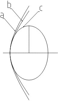
In the past, the roll shape design of the pinch roll was mostly hyperbolic design, the algorithm is simple, but the contact rate is quite low, such as figure 1 As shown in , the curve a is a hyperbolic type, and the curve c is the projected ellipse line of the tube and bar on the α angle plane. The contact rate of curve a is only 51%, while the deviation in diameter is as much as 17%.
When the metal blank is conveyed by such a roll shape, it will inevitably move in multiple directions, which will increase the difficulty of biting into the rolling mill and reduce the rolling accuracy

Method used


Image

  • Pinch roll for pipes and bars
  • Pinch roll for pipes and bars
  • Pinch roll for pipes and bars

Examples


Embodiment Construction

[0015] The present invention will be further described below in conjunction with the accompanying drawings and embodiments.

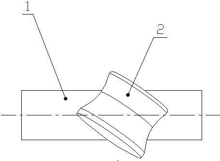
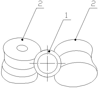
[0016] Such as figure 2 , 3 As shown, the two rollers 2 of the pinch roller device are arranged crosswise with the cylindrical blank 1, and the rollers 2 and the cylindrical blank 1 form an inclination angle α (such as Figure 4 shown). The cylindrical blank 1 is driven forward by the self-rotation of the roller 2, and the axis of the roller 2 and the intersection point of the roller 2 and the cylindrical surface of the cylindrical blank 1 are taken as a surface, and the cylindrical surface of the cylindrical blank 1 is cut with this surface, and the cylindrical blank 1 is cut to obtain an ellipse Shaped facets (such as Figure 5 shown), this ellipse edge is the best meshing curve.

[0017] Figure 4 , 5 Among them, d is the diameter of the cylindrical blank, a is the major axis of the elliptical section, b is the short axis of the elliptical sec...


PUM


Abstract

The invention relates to a pinch roll for pipes and bars. The shape of the circumferential surface of the roll comprises an improved hyperbolic curve as the upper part and an oval curve smooth transition as the lower part, wherein the improved hyperbolic curve of the upper part is as follows: cos<2>alphaX<2>-deltaY<2>=deltad<2>; and the oval curve of the lower part is as follows: cos<2>alphaX<2>+Y<2>=d<2>; wherein d is the diameter of a cylindrical blank, alpha is the included angle between the central axis of the roll and the central axis of the cylindrical blank, delta is a coefficient witha numerical range of 0.5-1, X represents a major axis, and Y represents a minor axis. In the pinch roll, two rollers of the pinch roll device and the cylindrical blank are arranged crosswise, and theself rotation of the rollers drives the cylindrical blank to move forward. By using the technical scheme, the roll curved surfaces of the rollers are brought in good contact with the blank. Thereby, the contact rate is ensured to the greatest extent, and the roll bite is smooth in the rolling process.

Description

technical field [0001] The invention relates to a pinch roller for pipe and rod. Background technique [0002] At present, the rolling of tubes and bars is widely used. Generally, a set of pinch roller device is used to transport the cylindrical blank on the production line. The two rollers of the pinch roller device are arranged crosswise with the cylindrical blank. The advance of the billet is beneficial for the billet to be bitten by the rolling mill. In the past, the roll shape design of the pinch roll was mostly hyperbolic design, the algorithm is simple, but the contact rate is quite low, such as figure 1 As shown in , curve a is hyperbolic, and curve c is the projected ellipse line of tube and bar on the α angle plane. The contact rate of curve a is only 51%, while the deviation in diameter is as much as 17%. When the metal blank is conveyed by such a roll shape, it will inevitably move in multiple directions, which will increase the difficulty of biting into the ro...

Claims


Application Information

Patent Timeline
Patent Type & Authority Patents(China)
IPC IPC(8): B21B39/02
Inventor 阎洪涛王业龙谢涛
Owner JINAN HEAVY MACHINERY JOINT STOCK
Learn More