

Automatically cutting and adhering machine
A bonding machine and automatic technology, which is applied to other household appliances, household appliances, household components, etc., can solve the problems of no integration, insufficient joint, high cost, etc., and achieve improved work efficiency, firm joint, and simple structure. Effect
- Summary
- Abstract
- Description
- Claims
- Application Information
AI Technical Summary
Problems solved by technology
Method used
Image

Examples
Embodiment 1
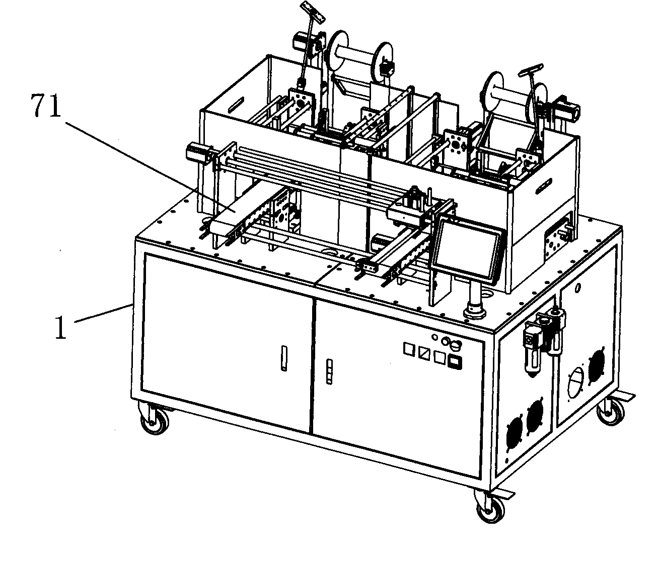
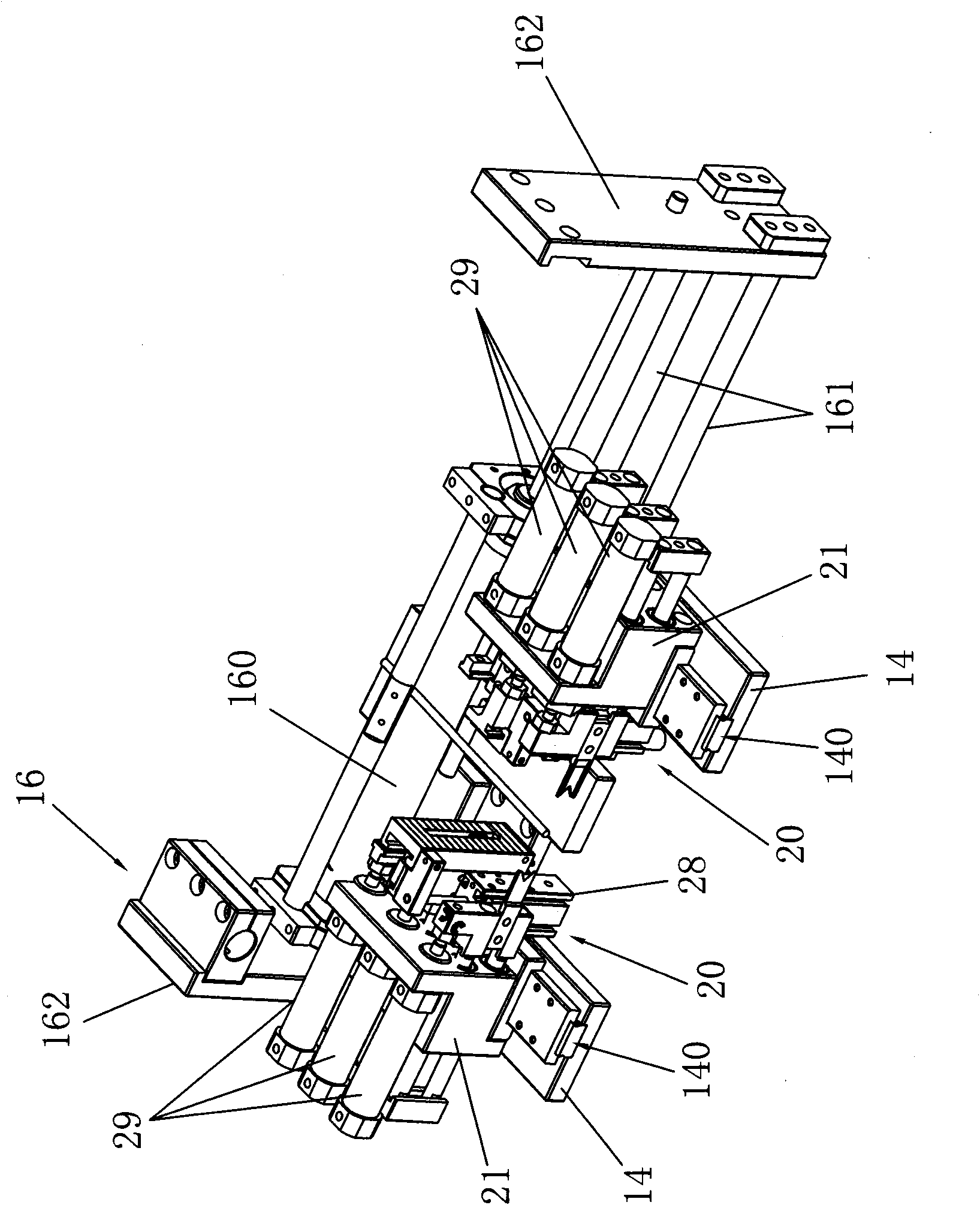
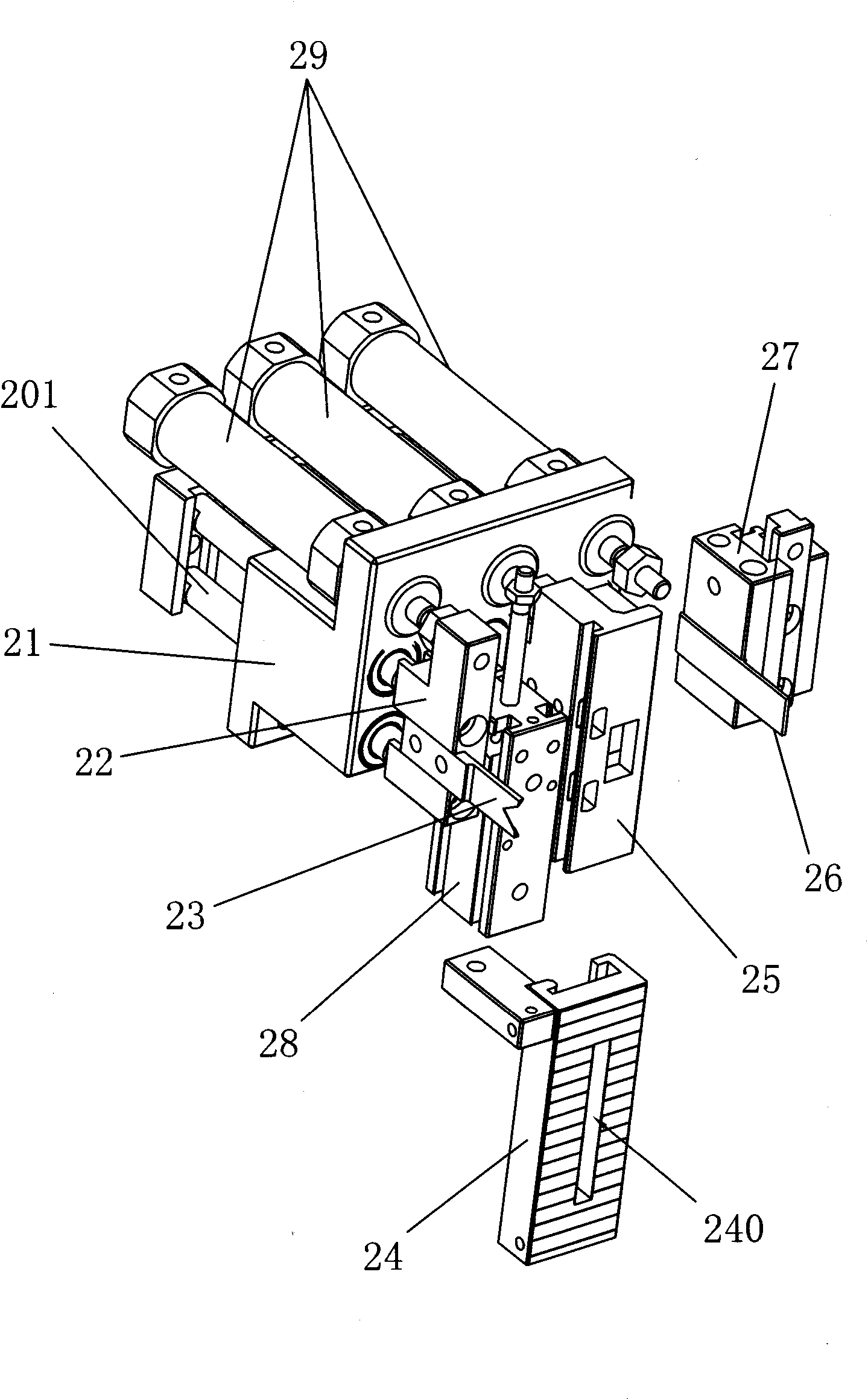
[0045] Embodiment one, such as Figure 1 to Figure 14 As shown, the automatic cutting and bonding machine includes a frame 1 and a control system, and it also includes a gear feeding device, a hot-press cutting device, a manipulator feeding and clamping device, a rotary glue feeding device and a conveying device that are sequentially arranged on the frame 1 ;The control system controls the connection of the gear feeding device, the hot-press cutting device, the manipulator feeding and clamping device, the rotary glue feeding device and the conveying device; under the control of the control system, the automatic cutting and bonding machine can automatically complete the entire manufacturing process of hair rings Among them, the gear feeding device completes the feeding process, the hot-press cutting device completes the hot-pressing and cutting process, the manipulator feeding and clamping device and the rotary glue feeding device jointly complete the gluing and bonding process,...
Embodiment 2
[0080] Embodiment two, such as Figure 15 with Figure 16 As shown, the difference from Embodiment 1 is that the automatic cutting and bonding machine described in Embodiment 2 also includes a tension detection device, which includes a detection support 81, a tension sensor 82, a first detection head 83 , a second detection head 84 that can move longitudinally, and a longitudinal motor 80 for driving the second detection head 84 to move longitudinally, the vertical motor 80 and the first detection head 83 are installed on the detection support 81, and the tension sensor 82 is connected to the first A detection head 83 , the output shaft of the longitudinal motor 80 is connected to the second detection head 84 . Wherein, the vertical motor 80 is a stepping motor, the first detection head 83 and the second detection head 84 are arranged side by side, the effect of the first detection head 83 and the second detection head 84 is to pull the hair ring, and the effect of the vertic...
PUM
 Abstract
Description
Claims
Application Information