Plate turning machine

A technology of turning machine and material plate, applied in the field of turning machine, can solve the problems such as cracking of crank welding, equipment overhaul, heavy maintenance workload, etc., and achieve the effect of reducing intermediate links, simple structure and low failure rate

Inactive Publication Date: 2010-10-20
CERI PHOENIX INDAL FURNACE CO TD
View PDF2 Cites 2 Cited by
  • Summary
  • Abstract
  • Description
  • Claims
  • Application Information

AI Technical Summary

Problems solved by technology

[0006] 2. Due to the large pulsating cyclic stress, cracking occurs frequently at the welding part of the crank root, which makes the maintenance and repair work of the equipment very heavy.

Method used


Image

  • Plate turning machine
  • Plate turning machine
  • Plate turning machine

Examples


Embodiment Construction

[0028] The following will clearly and completely describe the technical solutions in the embodiments of the present invention with reference to the accompanying drawings in the embodiments of the present invention. Obviously, the described embodiments are only some, not all, embodiments of the present invention. Based on the embodiments of the present invention, all other embodiments obtained by persons of ordinary skill in the art without making creative efforts belong to the protection scope of the present invention.

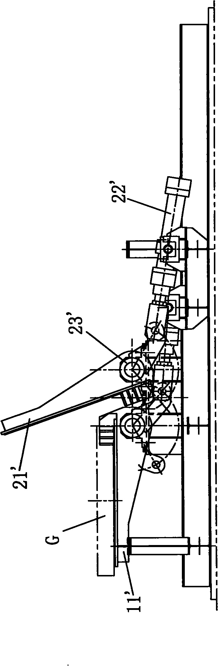
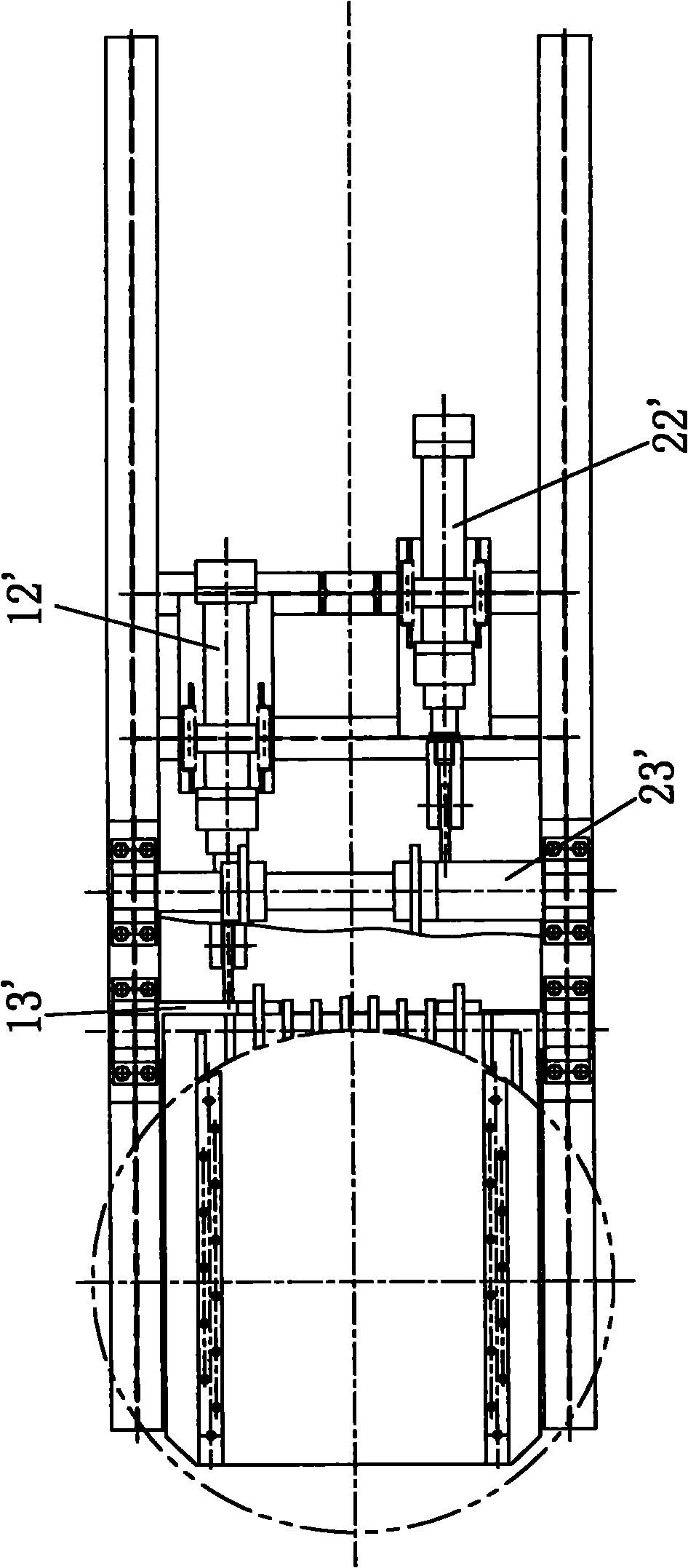
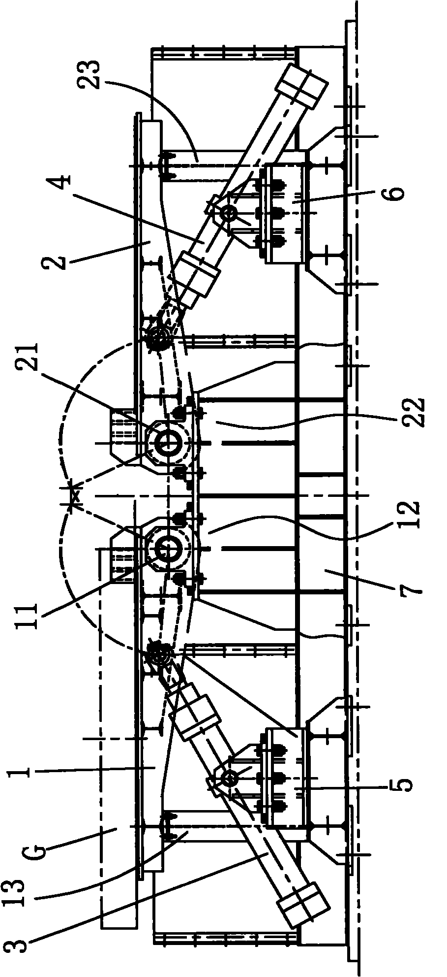
[0029] Cooperate image 3 and Figure 4 As shown, the plate turning machine proposed by the present invention includes a material receiving plate 1 , a material receiving plate 2 , a material receiving plate driver 3 and a material receiving plate driver 4 . The inboard end of feeding plate 1 (close to the end of feeding plate 2) is provided with feeding plate rotating shaft 11; The plate 2 is correspondingly arranged on one side of the feeding plate 1, and ...


PUM


Abstract

The invention discloses a plate turning machine which comprises a feeding plate, a receiving plate, a feeding plate driver and a receiving plate driver. A feeding plate rotating shaft is arranged at the inner side end of the feeding plate, a receiving plate rotating shaft is arranged at the inner side end of the receiving plate which is correspondingly arranged at one side of the feeding plate and forms a gap in between, one end of the feeding plate driver is directly connected with the feeding plate, the connection position of the feeding plate driver and the feeding plate is arranged at the outer side of the feeding plate rotating shaft, and the feeding plate can be driven by the feeding plate driver to rotate around the feeding plate rotating shaft. One end of the receiving plate driver is directly connected with the receiving plate, the connection position of the receiving plate driver and the receiving plate is arranged at the outer side of the receiving plate rotating shaft, and the receiving plate can be driven by the receiving plate driver to rotate around the receiving plate rotating shaft. In the invention, the feeding plate driver directly acts on the feeding plate, and the receiving plate driver directly acts on the receiving plate so that intermediate links, such as a crank, a driving shaft, and the like are canceled, and the plate turning machine has simpler structure and more reasonable stress.

Description

technical field [0001] The invention relates to a steel coil tray turnover device for a silicon steel annular heat treatment furnace in the metallurgical industry, which is an auxiliary tool and machine tool outside the silicon steel heat treatment line, and particularly relates to a plate turning machine. Background technique [0002] Currently, if figure 1 and figure 2 As shown, the relevant plate turning machine includes a feeding plate 11', a feeding plate driving hydraulic cylinder 12', a material receiving plate 21' and a material receiving plate driving hydraulic cylinder 22'. One end of the feeder plate 11' is provided with a feeder plate drive shaft 13', and the feeder plate drive hydraulic cylinder 12' is connected with the feeder plate drive shaft 13' through the feeder crank to drive the feeder plate 11' to rotate; One end of the material plate 21' is provided with a material receiving plate driving shaft 23', and the material receiving plate driving hydraulic...

Claims


Application Information

Patent Timeline
Patent Type & Authority Applications(China)
IPC IPC(8): C21D9/54
Inventor 曹瑞明李兵贾戈
Owner CERI PHOENIX INDAL FURNACE CO TD
Why Eureka
Try Eureka