
Roller type water injection well centering device

A technology for centralizers and water injection wells, applied in drilling equipment, wellbore/well components, measurement, etc., can solve the problems of long axial length of roller centralizers, large contact area of ​​the inner wall of the pipe string, affecting the installation of instruments in the pipe, etc. Achieve the effect of compact structure, easy construction and debugging, and simple parts processing

Inactive Publication Date: 2010-10-20
HARBIN INST OF TECH
View PDF5 Cites 6 Cited by
  • Summary
  • Abstract
  • Description
  • Claims
  • Application Information

AI Technical Summary

Problems solved by technology

[0003] The purpose of the present invention is to solve the problems that existing nylon centralizers and leaf spring centralizers have a large contact area with the inner wall of the pipe string, relatively large friction force, and the axial length of the roller centralizer is long, which affects the installation of instruments in the pipe. Provide a roller type water injection well centralizer

Method used


Image

  • Roller type water injection well centering device
  • Roller type water injection well centering device
  • Roller type water injection well centering device

Examples


specific Embodiment approach 1

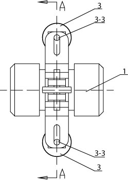
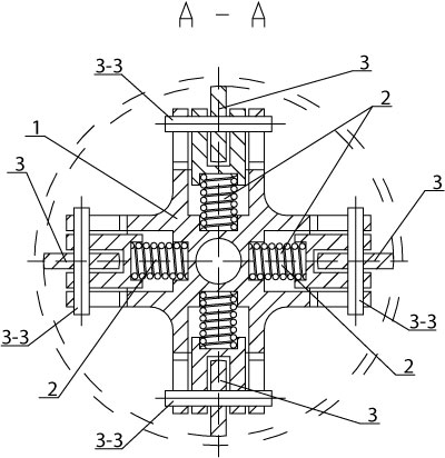
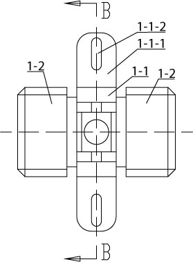
[0007] Specific implementation mode one: combine Figure 1 to Figure 6 Describe this embodiment. This embodiment includes a centralizer main body 1, four compression springs 2 and four roller assemblies 3. The centralizer main body 1 is composed of a cross-shaped slide plate 1-1 and two bolt heads 1-2. Two bolt heads The head 1-2 is arranged symmetrically at the center of both sides of the cross-shaped slide plate 1-1, and the cross-shaped slide plate 1-1 is integrated with two bolt heads 1-2, and each bolt head 1-2 on the cross-shaped slide plate 1-1 The outer end surface of the support arm 1-1-1 is provided with a mounting groove 1-1-2, and the mounting groove 1-1-2 divides the support arm 1-1-1 into two side walls 1-1-3, each There is a long hole 1-1-4 on the side wall 1-1-3, and the long holes 1-1-4 on the corresponding two side walls 1-1-3 are the same and facing each other. The installation groove 1-1-4 The bottom surface of 1-2 is provided with first blind hole 1-1-5, ...

specific Embodiment approach 2

[0008] Specific implementation mode two: combination Figure 5 Describe this embodiment, the junction of the wheel surface and the end surface of the roller 3-1 of this embodiment is a garden arc surface. This design can reduce the contact area between the wheel surface of the roller 3-1 and the inner wall of the water injection well pipeline, thereby reducing friction. When the inner diameter of the pipeline exceeds the maximum diameter of the centralizer for reliable centralization, replace it with a roller with a larger diameter and a matching slider. Other compositions and connections are the same as those in the first embodiment.

specific Embodiment approach 3

[0009] Embodiment 3: The material of the roller 3-1 in this embodiment is polytetrafluoroethylene or oil-impregnated nylon. The roller of the existing roller centralizer is rigid, and the contact with the inner wall of the water injection well pipeline is rigid, which requires high precision of the pipeline, and the centralization effect is poor after wear and tear. The roller 3-1 of the present invention adopts the above-mentioned material, so that the roller 3 -1 is in non-rigid contact with the inner wall of the water injection well pipeline, so the roller 3-1 will not damage the inner wall of the water injection well pipeline. Other compositions and connection relations are the same as those in Embodiment 1 or 2.


PUM


Abstract

A roller type water injection well centering device relates to a water injection well centering device. The invention aims to solve the problems that the existing nylon centering device and spring leaf centering device have large contact surface and friction force with the inner wall of the tubing string and the roller centering device has long axial length so as to influence the installation of instruments in the tube. The main body of the centering device comprises a cross sliding plate and two bolt heads which are integrated together, wherein each arm of the cross sliding plate is providedwith an installation slot, the long holes on the two side walls are the same and opposite, the bottom surface of each installation slot is provided with a first blind hole, a roller is arranged in a roller slot, the roller is connected with a slide block through a long pin, one roller component is arranged in each installation slot on the cross sliding plate, the two ends of the long pin of the roller component separately penetrate through the corresponding long hole, and a compressed spring is arranged between each first blind hole and each second blind hole. The invention is used for centering the testing instrument and the inner wall of the water injection well when the oilfield water injection well is tested.

Description

technical field [0001] The invention relates to a water injection well centralizer. Background technique [0002] In the process of testing water injection wells in oil fields, it is often necessary to ensure that the test instrument is coaxial with the injection well string, such as electromagnetic and ultrasonic flowmeters. At the same time, for the convenience of construction, the length of the centralizer must be limited to the greatest extent, and the friction between the centralizer and the inner wall of the pipe string must be reduced as much as possible during the downhole process. At present, spring centralizers, roller centralizers and nylon centralizers with spiral grooves in the axial direction are commonly used as centralizers for water injection wells. Among them, the nylon centralizer has a large contact area with the inner wall of the pipe string, the friction is large, the material cost is high, and it is a rigid contact. Rigid contact requires high precis...

Claims


Application Information

Patent Timeline
Patent Type & Authority Applications(China)
IPC IPC(8): E21B17/10E21B47/00
Inventor 张广玉宋文平徐明陈华南吕岩张如意
Owner HARBIN INST OF TECH
Learn More