Speed measuring and positioning method of single-row light source Z-type reflected light screen targets

A positioning method and technology of a light curtain target, applied in the direction of using a device for measuring the time required to move a certain distance, a measuring device, using re-radiation, etc., to achieve the effect of simple method, cost saving, and expanding the size of the target body

Inactive Publication Date: 2010-10-20
NANJING UNIV OF SCI & TECH
View PDF1 Cites 23 Cited by
  • Summary
  • Abstract
  • Description
  • Claims
  • Application Information

AI Technical Summary

Problems solved by technology

[0006] The four light curtain target method can measure the position and velocity of the projectile's target point, but it needs four sets of light sources and light detectors
Although this method can measure the velocity of the projectile and the coordinates of the target point, it uses two sets of light sources and light detectors

Method used


Image

  • Speed measuring and positioning method of single-row light source Z-type reflected light screen targets
  • Speed measuring and positioning method of single-row light source Z-type reflected light screen targets
  • Speed measuring and positioning method of single-row light source Z-type reflected light screen targets

Examples


Embodiment

[0034] 1. Example of derivation process

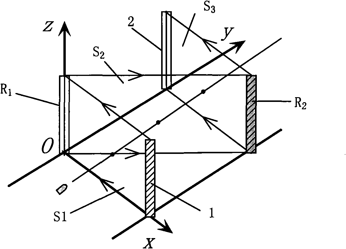
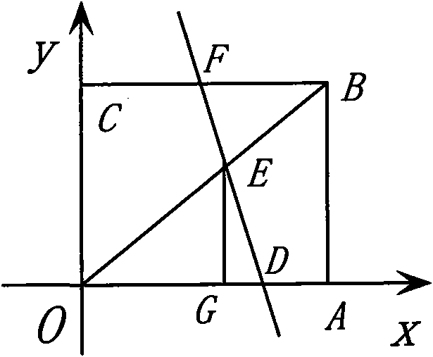
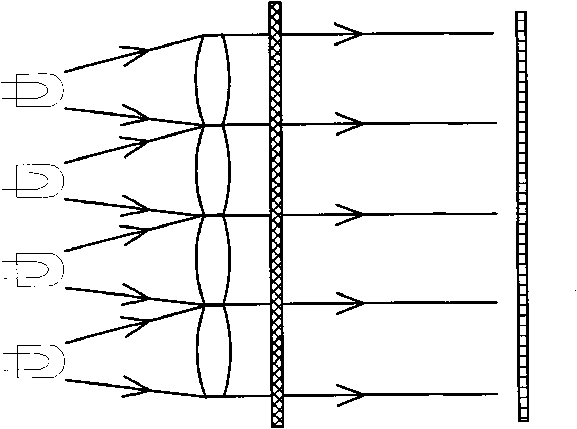
[0035] exist figure 1 , a single row of parallel light sources 1 emits parallel light to form the first light curtain S 1 , the first light curtain S 1 Through the first mirror R 1 After reflection, the second light curtain S is formed 2 , the second light curtain S 2 After the second mirror R 2 After reflection, a third light curtain S is formed 3 , in the third light curtain S 3A light detector 2 is placed at the end to form a light curtain target. The width of the light curtain target in the x direction is denoted as a, and the light curtain S 1 with light curtain S 3 The distance is b, and the values ​​of a and b depend on the size of the projectile and the actual required target area. Light curtain S 1 , S 2 , S 3 The projection in the xOy plane is zigzag.

[0036] When the projectile passes through the target body of the light curtain, it passes through the light curtain S in sequence 1 , S 2 , S 3 , after the pr...


PUM


Abstract

The invention discloses a speed measuring and positioning method of single-row light source Z-type reflected light screen targets, comprising the following steps of: forming a first path of light screen by parallel light emitted by single-row parallel light sources; reflecting the first path of light screen by a first reflection mirror to form a second path of light screen; reflecting the second path of light screen by a second reflection mirror to form a third path of light screen; placing a photodetector at the tail end of the third path of light screen; correspondingly measuring the time on penetrating through the light screen when bullets penetrate through the first path of light screen, the second path of light screen and the third path of light screen in sequence; indirectly solving the speed of the bullets penetrating through the targets and two coordinates of cross points of the bullets with the second path of light screen on the vertical planes of the first path of light screen, the second path of light screen and the third path of light screen according to the time difference and the target body size; obtaining the positions of the bullets for shielding the light rays through the photodetector, i.e. obtaining coordinates of cross points of the bullets with the second path of light screen in the array direction of a photosensitive element of the photodetector; and transmitting a measuring result to display equipment or a computer for further processing. The invention can be used for conveniently measuring target landing point coordinates of the bullets and the bullet speed at one step.

Description

technical field [0001] The invention belongs to the technique of measuring projectile velocity and the coordinates of the impact point, in particular to a single-row light source Z-type reflective light curtain target speed measurement and positioning method. Background technique [0002] The invention relates to an automatic target reporting device for bullet shooting and a method for measuring the velocity of a projectile. It can be used for automatic target reporting in military shooting training, sports shooting training and competitions, mass entertainment shooting activities, etc. It can also be used in military scientific research and even weapon acceptance to measure the position and speed of projectiles. [0003] In addition to the traditional artificial target reporting technology, the existing impact point detection methods mainly use sound, light, electricity and other methods. For example, the conductive rubber target method, the coordinate target based on imag...

Claims


Application Information

Patent Timeline
Patent Type & Authority Applications(China)
IPC IPC(8): G01P3/68G01B11/00
Inventor 于纪言王晓鸣李永新李文斌高旭东
Owner NANJING UNIV OF SCI & TECH
Why Eureka
Try Eureka