Optical lens for ultraviolet laser

An optical lens, ultraviolet laser technology, applied in the field of optical lens, can solve the problems of affecting the focusing of ultraviolet laser, the product is not fine and clear enough, etc.

Active Publication Date: 2010-10-20
HANS LASER TECH IND GRP CO LTD
View PDF2 Cites 13 Cited by
  • Summary
  • Abstract
  • Description
  • Claims
  • Application Information

AI Technical Summary

Problems solved by technology

[0006] The purpose of the present invention is to provide an optical lens for ultraviolet laser application, which aims to solve

Method used


Image

  • Optical lens for ultraviolet laser
  • Optical lens for ultraviolet laser
  • Optical lens for ultraviolet laser

Examples


example

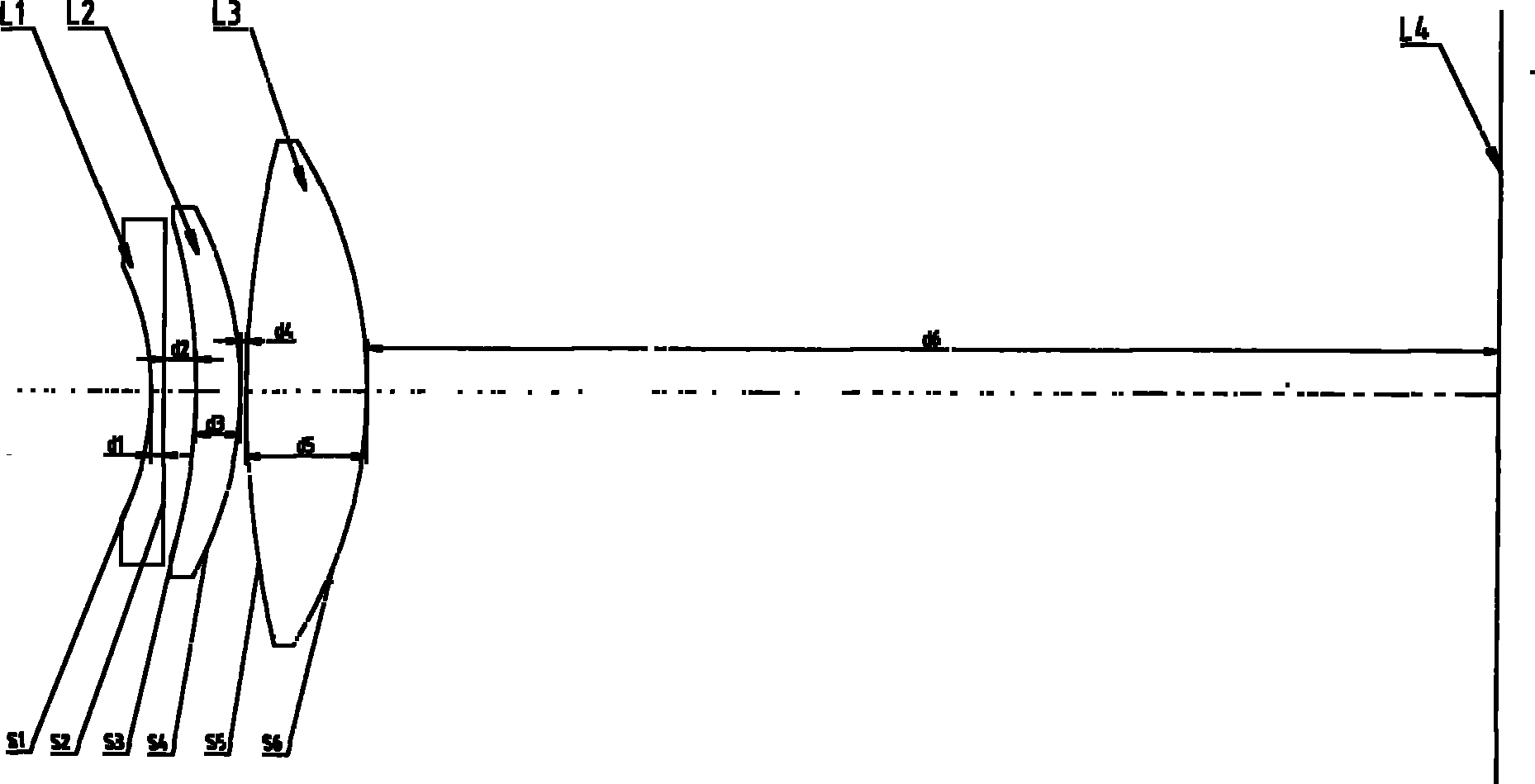
[0029] The first lens L1 is composed of two curved surfaces S1 and S2 whose radii of curvature are R1=-45mm and R2=1500mm respectively, the central thickness d1=3mm on the optical axis, and the material is Nd1:Vd1 is about 1.5 / 70; the second Lens L2 is composed of two curved surfaces S3 and S4 with curvature radii of R3=-110mm and R4=-68mm respectively, the central thickness d3=6mm on the optical axis, and the material is Nd3: Vd3 is about 1.6 / 41; the third lens L3 is composed of two curved surfaces S5 and S6 with curvature radii of R5=770mm and R6=-72mm respectively, the central thickness d5=6mm on the optical axis, and the material is Nd5:Vd5 is about 1.6 / 41; the first lens L1 and The distance between the second lens L2 on the optical axis is d2=4mm, the distance between the second lens L2 and the third lens L3 on the optical axis is d4=0.1mm, and the distance between the third lens L3 and the imaging surface L4 on the optical axis The distance is d6=110mm.

[0030] The lis...


PUM


Abstract

The invention relates to an optical lens for an ultraviolet laser. The optical lens is characterized by comprising a first lens, a second lens and a third lens which are sequentially positioned in the incident direction of beams, wherein the first lens is a biconcave lens, the second lens is a crescent lens, and the curved surfaces of the first and second lenses both bend towards the incident direction of rays; and the third lens is a biconcave lens. The optical lens is used for the ultraviolet laser with focal length of 254mm and wavelength of 355mm and a processing area with processing range of 160mm<2>*160mm<2>. A concept of high-order aberration mutual compensation is adopted in aberration correction so as to obtain good effect; the ultraviolet laser after being focused by the lens has small light spot and concentrated energy and can perform superfine processing; and the processed product is finer and clearer.

Description

【Technical field】 [0001] The invention relates to an optical lens for ultraviolet laser application. 【Background technique】 [0002] With the continuous development of laser processing, the types of media to be processed are increasing, and the processed effects are required to be more and more refined, especially for some special materials, which have different requirements for the wavelength of the laser. Some materials can no longer meet the processing requirements of these media with the laser wavelengths λ=1064nm and 532nm commonly used in the past; there are also some materials that can be processed by lasers with wavelengths of 1064nm and 532nm, but in order to achieve more fine and clear effects , or switch to short-wave ultraviolet laser processing, because its focusing spot is extremely small, as shown in the following formula: [0003] Rayleigh spot diameter δ=2.44λf / D [0004] It can be seen from the above formula that when using the same f / D optical lens, when...

Claims


Application Information

Patent Timeline
IPC IPC(8): G02B13/14G02B13/18B23K26/36
Inventor 李家英周朝明高云峰
Owner HANS LASER TECH IND GRP CO LTD
Why Eureka
Try Eureka