
Integrator and light irradiation apparatus

A technology of a light irradiation device and an integrator, which is applied in the field of integrators, and can solve the problems of integrator optical characteristic changes, position offset, and exposure accuracy reduction, etc.

Inactive Publication Date: 2010-10-20
USHIO DENKI KK
View PDF1 Cites 2 Cited by
  • Summary
  • Abstract
  • Description
  • Claims
  • Application Information

AI Technical Summary

Problems solved by technology

If the thermal expansion of the frame of the lens group is maintained, for example, the position shift (alignment shift) between the light incident side lens group and the light exit side lens group will occur, and the optical characteristics of the integrator will change, which may also lead to a decrease in exposure accuracy. situation

Method used


Image

  • Integrator and light irradiation apparatus
  • Integrator and light irradiation apparatus
  • Integrator and light irradiation apparatus

Examples


Embodiment Construction

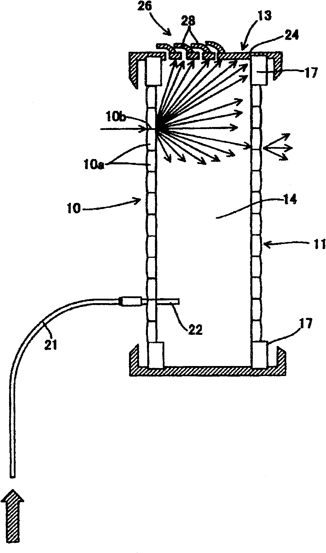
[0049] figure 1 It is a cross-sectional explanatory view showing the integrator of the present invention, and the light-incident-side lens group 10 and the light-exit-side lens group 11 are connected by a cylindrical frame 13 to form an internal space 14 .

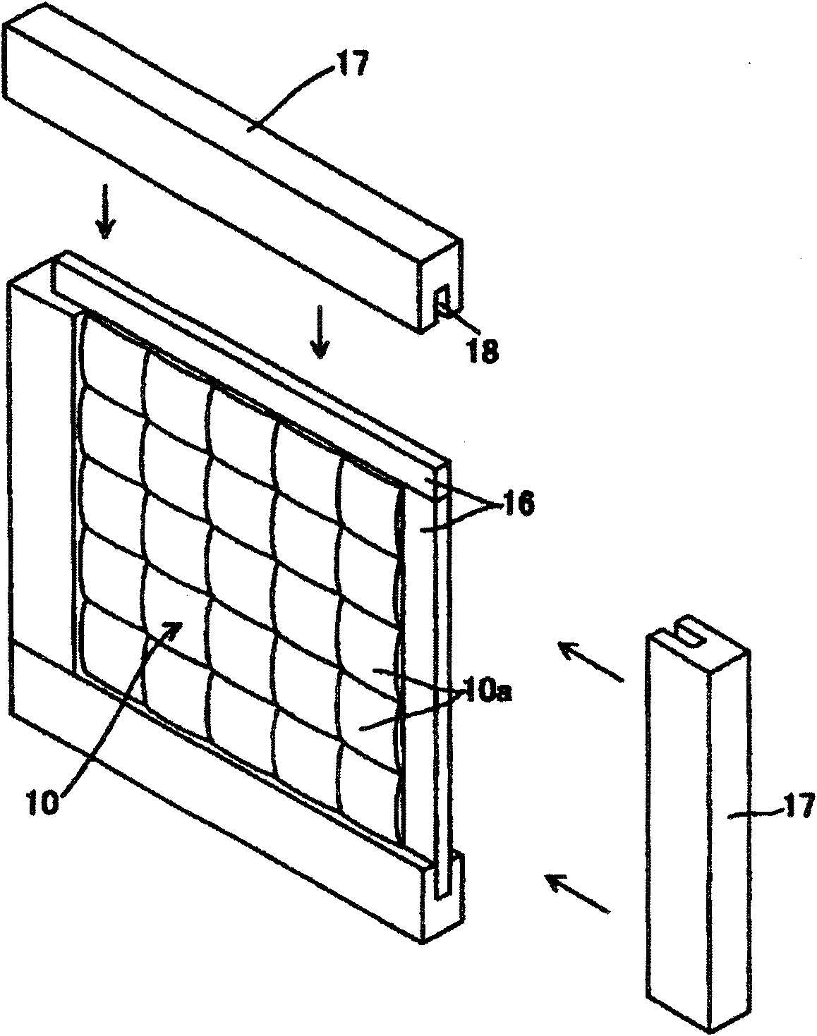
[0050] exist figure 2 In the figure, an example of the configuration of the light incident side lens group 10 (or the light exit side lens group 11 ) of the above-mentioned two combined integrators is shown. In addition, this figure is an example when the shape of each lens is a square.

[0051] In the lens group 10, a plurality (in this example, a total of 25) of lenses 10a, 10a are fused (fused) with low-melting-point glass to be integrated. Next, a glass-made holding piece 16 is welded to its periphery.

[0052] The holding piece 16 around the periphery of the welded and integrated lens group 10 is fitted into a groove 18 formed in the metal lens holder 17 .

[0053] The lens group 10 thus held by the lens holder 17...


PUM


Abstract

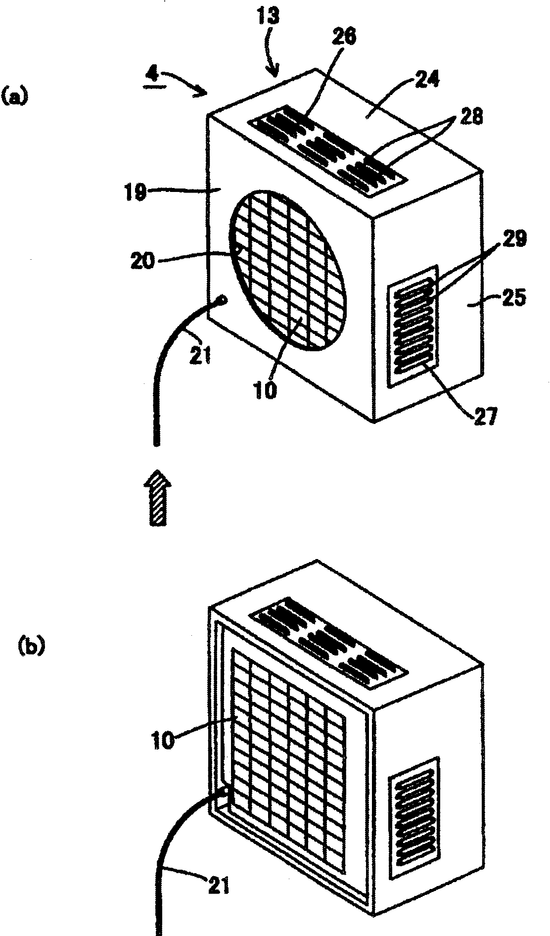
The present invention provides an integrator which comprises the following components: a light incidence side lens set, a light emission side lens set and a frame for connecting the lens sets. A structure of the integrator is brought forward, which is characterized in that the diffused light from an interface of the lenses that form the light incidence side lens side does not leak to outside of the frame, and furthermore temperature increase of the frame, etc. is prevented. The invention is characterized in that: the cooling medium such as air is introduced into an inner space which is surrounded by the light incidence side lens set, the light emission side lens set and the frame for connecting the lens sets. Furthermore the invention is further characterized in that a cooling medium outlet of the cylindrical frame is provided with a light shielding component.

Description

technical field [0001] The present invention relates to an integrator for uniform illuminance distribution in a light irradiation area in a light irradiation device, in particular to an integrator with lens groups on the light incident side and the light exit side. In addition, it relates to a light irradiation device using the integrator, and particularly relates to a light irradiation device used as a light source device such as an exposure device. Background technique [0002] Conventionally, in a light irradiation device used as a light source device such as an exposure device, an integrator for making the illuminance distribution on the light irradiation surface uniform is used, as shown in Japanese Patent Application Laid-Open No. 56-81813. As an integrator, an integrator composed of a so-called rod lens, or an integrator composed of a pair of light-incident-side lens groups and a light-exit-side lens group is known. [0003] exist Figure 4 A configuration example of...

Claims


Application Information

Patent Timeline
Patent Type & Authority Applications(China)
IPC IPC(8): G02B27/09G02B7/02G03F7/20
CPCG02B27/0961G02B27/18G02B2207/123G03F7/2008
Inventor 铃木一好
Owner USHIO DENKI KK
Learn More