Landing flap mechanism driven by pinion gears

A pinion and flap technology, applied in the field of trailing edge flap devices

Inactive Publication Date: 2010-10-20
AIRBUS OPERATIONS GMBH
View PDF4 Cites 12 Cited by
  • Summary
  • Abstract
  • Description
  • Claims
  • Application Information

AI Technical Summary

Problems solved by technology

Conventional screw drives, hydraulic drives or bevel gear drives and the associated kinematics cannot meet the stated requirements for a particularly small installation space

Method used


Image

  • Landing flap mechanism driven by pinion gears
  • Landing flap mechanism driven by pinion gears
  • Landing flap mechanism driven by pinion gears

Examples


Embodiment Construction

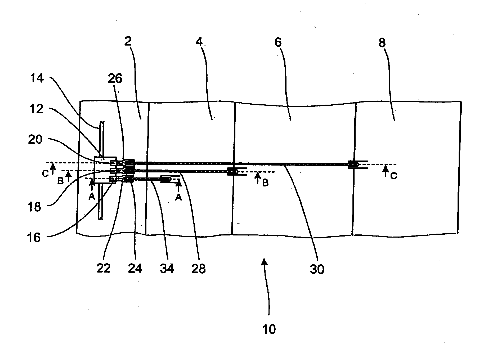
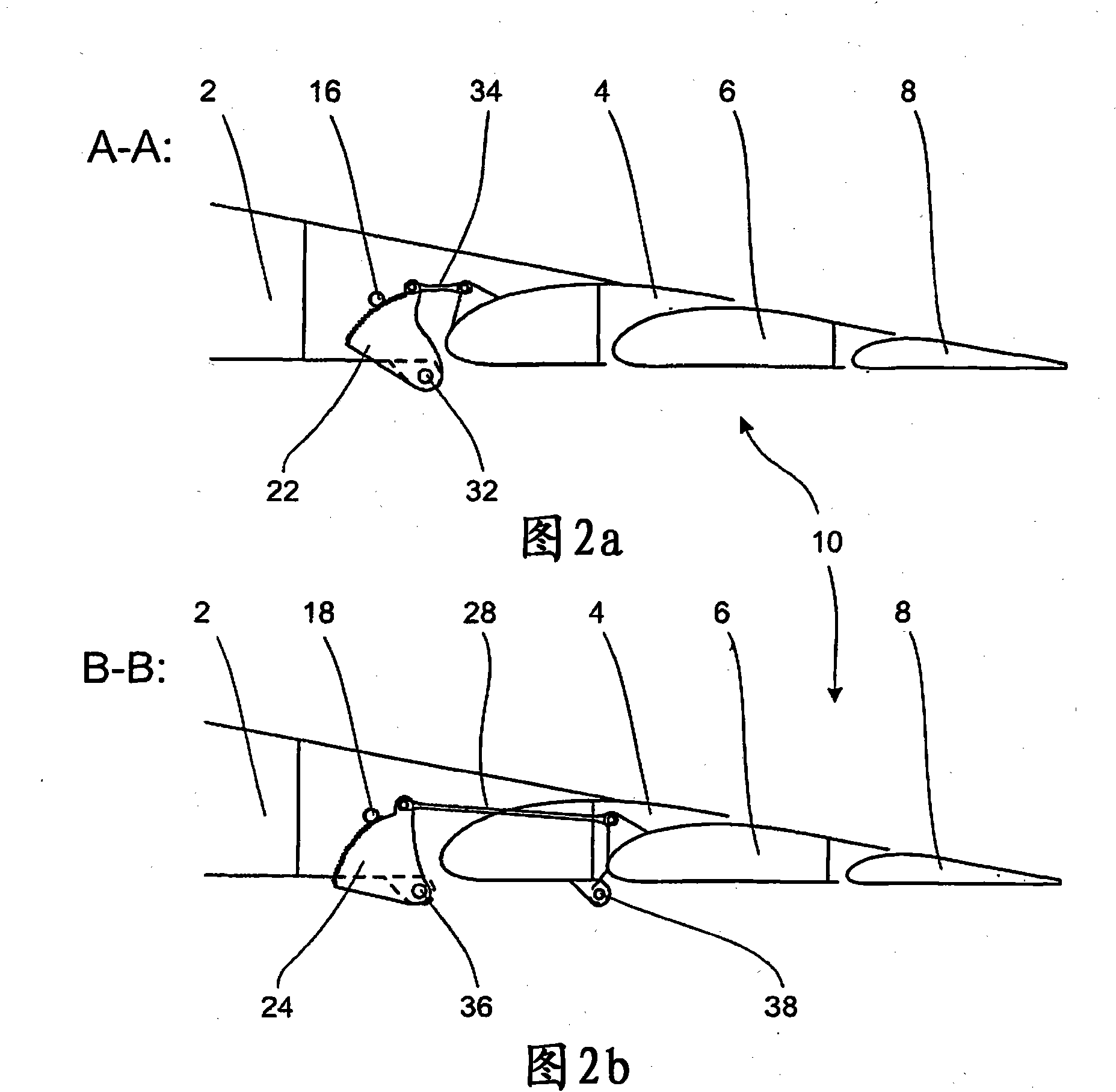
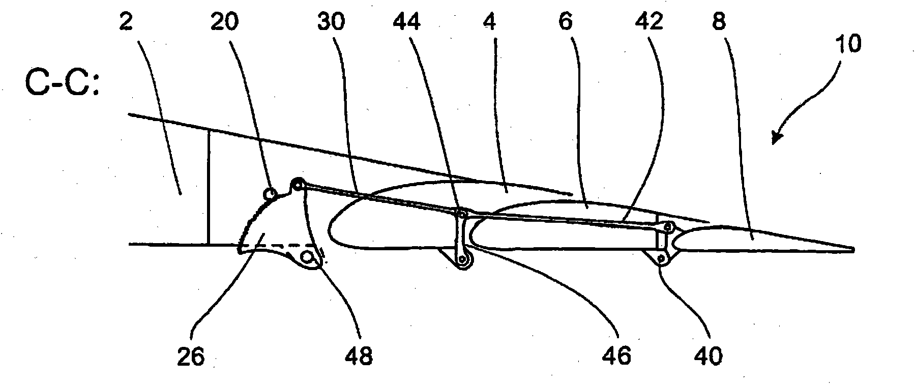
[0017] figure 1 Shown is a wing 2 with a trailing edge flap 10 consisting of three flap sections 4 , 6 and 8 . In the exemplary embodiment described, a central drive 12 is provided in a fixed manner to the wings, into which two drive shafts 14 , driven approximately by one or more electric motors, lead. Alternatively, the drive can take place via a central hydraulic drive, such as in conventional high-lift systems with shaft drives for both wings. In the alternative to the shaft drive, a shaft guide to the wing-fuselage transition is necessary.

[0018] The central drive 12 drives three pinions 16, 18 and 20 which in turn engage in three toothed discs 22, 24 and 26 which Preferably there are teeth on the circumferential parts facing the respective pinions 16 , 18 and 20 . Sprockets 22, 24 and 26 are mounted on the bottom of the central drive 12 or on the wing 2 figure 1 at the hinge point not shown. Pinions 16 , 18 and 20 provide drive torque and motion to flap segments 4...


PUM


Abstract

The invention relates to a device for moving a trailing edge flap (10) on an aircraft wing (2), wherein the trailing edge flap comprises one or more flap segments (4, 6, 8), a first flap segment (4) being movably mounted on the wing (2) and connected to a first toothed moving element (22) driven by a first pinion (16).

Description

technical field [0001] The invention relates to a device for moving a trailing edge flap of an aircraft wing, in which device the trailing edge flap has one or more flap segments. Background technique [0002] Such a device is preferably designed in such a way that the kinematics of the trailing edge flap and the drive of the kinematics interact in an optimal manner to bring about the desired movement sequence and the predetermined deflection of the trailing edge flap. A preferred drive is established here, such as a screw drive, hydraulic drive or bevel gear drive. In screw drives or bevel gear drives, the drive rod extends over a wide area of ​​the wing from a central drive unit, which is located in the wing-body-transition, to the trailing edge flap. At the same time, the kinematics of the trailing edge flap to be moved are often realized by expensive guides with rails or pulleys. The above-mentioned drives and the associated kinematics usually require installation spac...

Claims


Application Information

Patent Timeline
Patent Type & Authority Applications(China)
IPC IPC(8): B64C9/16B64C9/20B64C13/34B64C13/38
CPCB64C9/16B64C9/20
Inventor 雷纳·加特尔曼
Owner AIRBUS OPERATIONS GMBH
Why Eureka
Try Eureka