Feeding mechanism of numerical control turret punch press in X-axis direction

A technology of CNC turret punch press and feeding mechanism, which is applied to feeding devices, metal processing equipment, manufacturing tools, etc., can solve problems such as complicated operation, and achieve the effects of simplified mechanical structure, safe and reliable work, and fewer failures

Inactive Publication Date: 2010-10-27
JINAN CASTING FORGING MACHINERY INST
View PDF4 Cites 8 Cited by
  • Summary
  • Abstract
  • Description
  • Claims
  • Application Information

AI Technical Summary

Problems solved by technology

Although this structure is the most commonly used structure on the turret punch press, because the clamp needs to manually adjust the clamping position, and it needs to be used in conjunction with the repositioning cylinder to realize the re-clamping of the sheet during the repositioning process, the operation is complicated

Method used


Image

  • Feeding mechanism of numerical control turret punch press in X-axis direction
  • Feeding mechanism of numerical control turret punch press in X-axis direction
  • Feeding mechanism of numerical control turret punch press in X-axis direction

Examples


Embodiment 1

[0028] Embodiment 1: A turret punch press powered by a linear motor in the X direction feeds components.

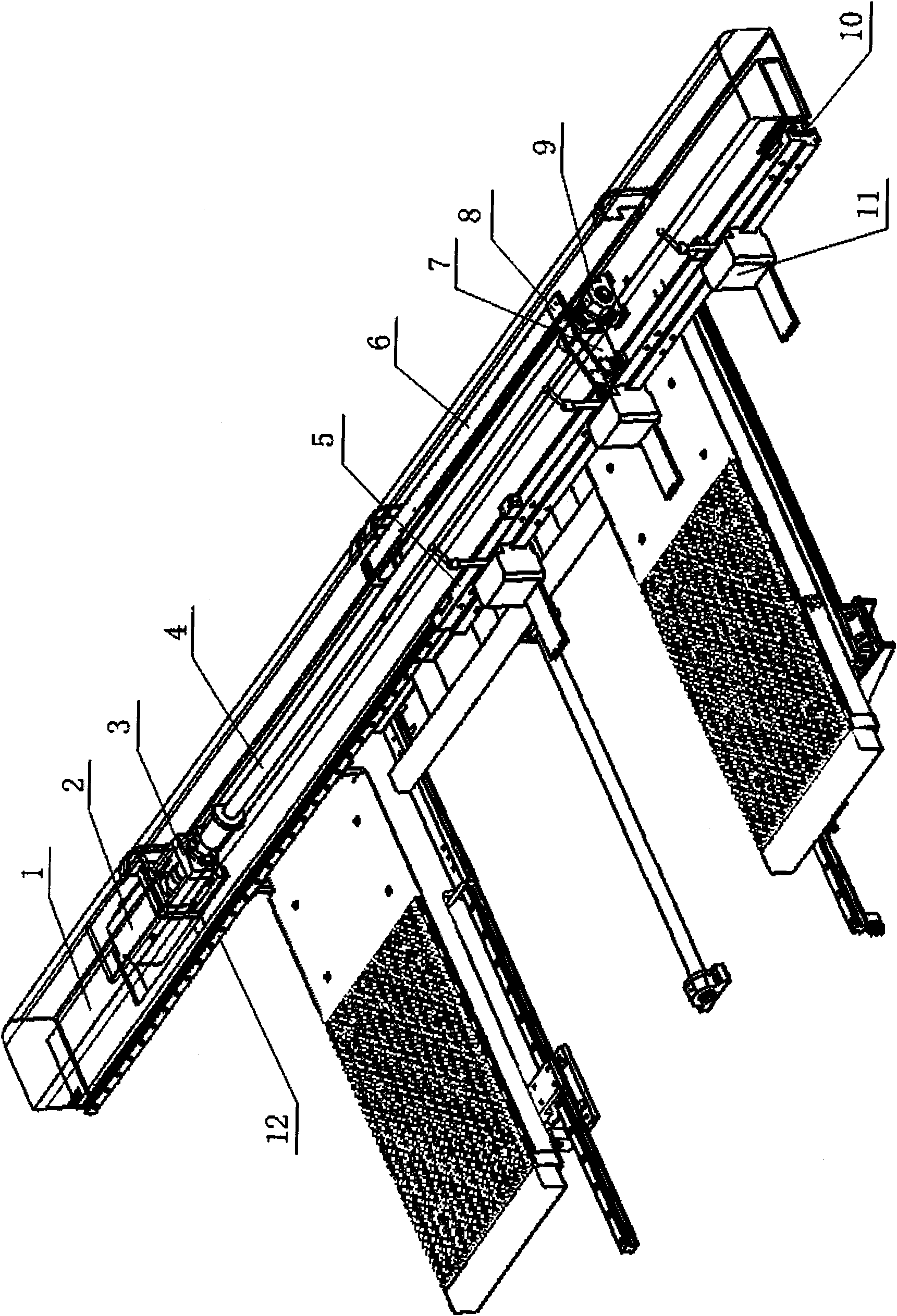
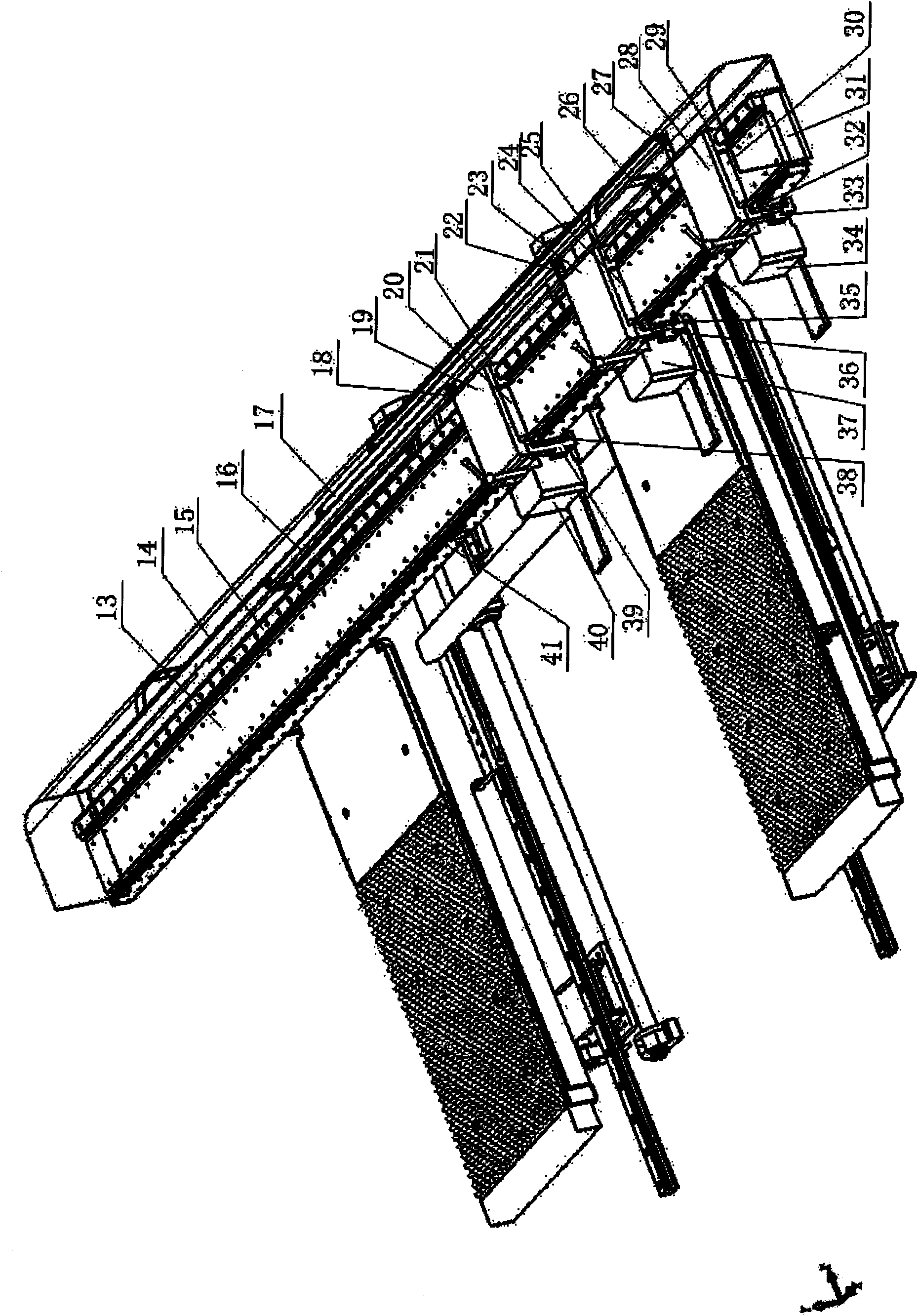
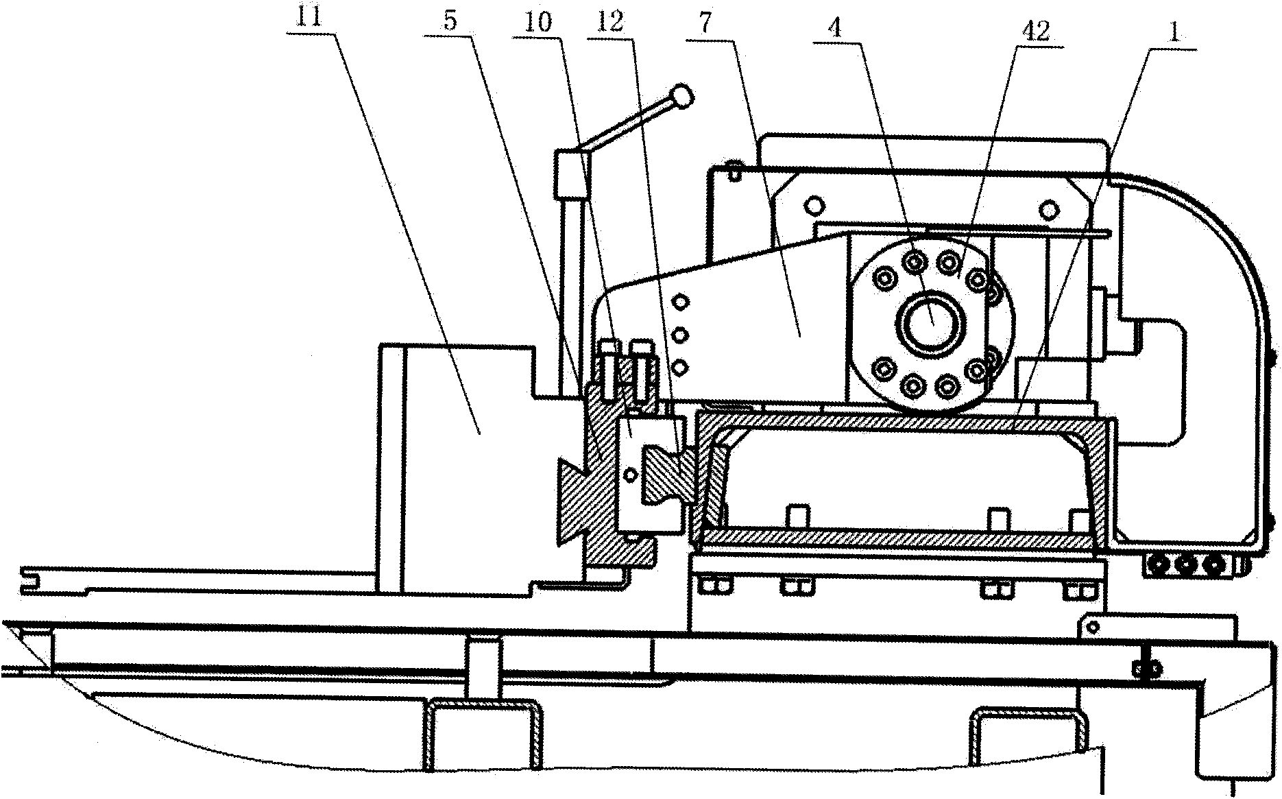
[0029] Such as figure 2 , 4 6. As shown in 6: the feeding parts powered by the linear motor in the X direction include beam 31, guide rail I15, guide rail II41, linear motor stator 13, coupling frame I, coupling frame II, coupling frame III, linear motor mover I20, linear motor Motor mover Ⅱ24, linear motor mover Ⅲ30, clamp Ⅰ34, clamp Ⅱ37, clamp Ⅲ40. When the mover of the linear motor moves on the stator of the linear motor, the corresponding coupling frame also moves together under the drive of the mover of the linear motor, thereby realizing the movement of the clamp driven by the coupling frame. Since the wires corresponding to the mover I20 of the linear motor are arranged through the drag chain I16, the wires corresponding to the mover II24 of the linear motor are arranged through the drag chain II17, and the wires corresponding to the mover III30 of the linear mo...

Embodiment 2

[0030] Example 2: Repositioning of Feed Part Grippers Powered by Linear Motors.

[0031] Servo repositioning of the clamp eliminates the need for previously fed parts (such as Figure 5 ) during repositioning, the operation of pressing down the sheet material by the action of two repositioning cylinders 44 on the bed 45 . When one of the three clamps adjusts its position, the other two remain clamped, that is, one clamp releases the sheet, and the position of the linear motor mover on the linear motor stator on the clamp seat plate that is matched with it is adjusted by numerical control , after the clamp is moved to the set position and clamped, a displacement is completed. When repositioning is required, keep the two clamps clamping the sheet, and adjust the displacement of the other clamp. Next, according to the actual situation, you can see how many clamps need to be displaced to achieve clamp repositioning. Through The combined displacement of the clamps by the program ...


PUM


Abstract

The invention relates to a feeding mechanism of a numerical control turret punch press in X-axis direction, which comprises a cross beam arranged on a body of the numerical control turret punch press. The invention is characterized in that the outer side of the top surface of the cross beam is provided with a guide rail I; one side surface adjacent to the top surface is provided with a guide rail II which is parallel to the guide rail I; the cross beam between the guide rail I and the guide rail II is fixed with a linear motor stator; the cross beam is provided with three coupling brackets which stretch across the cross beam through the guide rail I and the guide rail II; each connecting bracket is provided with a slider and a side slider which respectively cooperate with the guide rail I and guide rail II; the coupling bracket is also provided with a linear motor rotor which cooperates with the linear motor stator; and pliers are fixed on the side slides through a plier seat.

Description

technical field [0001] The invention relates to a numerically controlled turret punching machine, in particular to an X-axis feeding device which is powered by a linear motor and can realize servo positioning of clamps. Background technique [0002] The CNC turret punch press is the key equipment for sheet metal stamping processing. As a feeding device for automatic feeding of sheet metal, the traditional technology can be found in figure 1 , the motor 2 is used to drive the ball screw 4 to realize the power transmission, and it is guided by the guide rail 12 and the slider 10 . Such as image 3 The shown connecting seat 7 is connected with the lead screw sleeve 42 by screws. On the beam 1, the motor 2 fixed on the motor seat 3 drives the ball screw 4 to rotate. The top of the lead screw 4 moves back and forth along the X direction, the coupling seat 7 and the slide plate 5 are also connected by screws, the slide plate 5 and the slider 10 are connected by screws, and the s...

Claims


Application Information

Patent Timeline
Patent Type & Authority Applications(China)
IPC IPC(8): B21D43/10
Inventor 李兵
Owner JINAN CASTING FORGING MACHINERY INST
Why Eureka
Try Eureka