
Wireless ground penetrating radar system

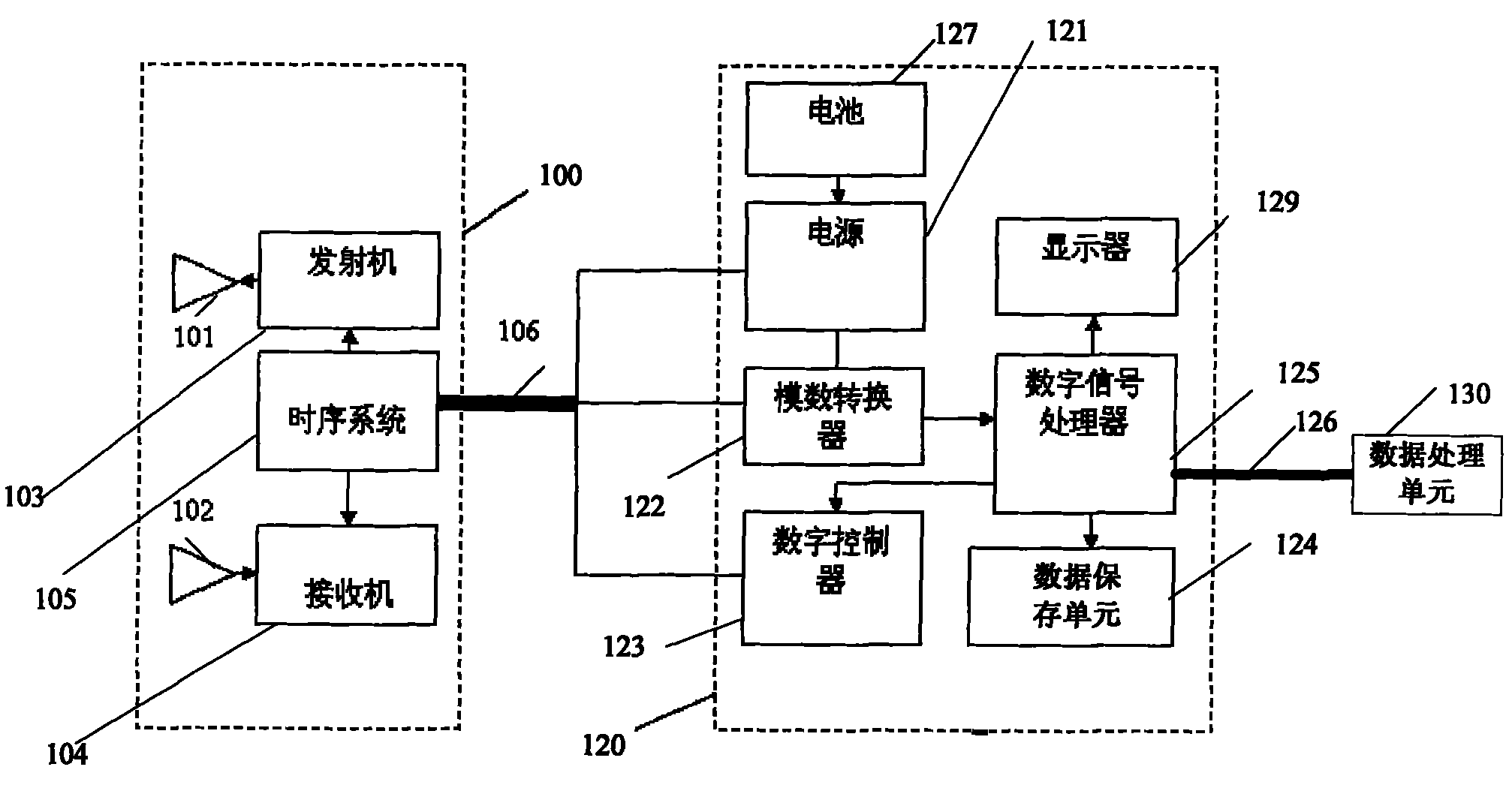
A ground penetrating radar, wireless technology, applied in radio wave measurement system, wireless communication, radio wave reflection/reradiation, etc. The control box 120 and the data processing unit 130 are heavy, etc.

Inactive Publication Date: 2010-10-27
武汉天毅达电子科技有限公司 +1
View PDF3 Cites 21 Cited by
  • Summary
  • Abstract
  • Description
  • Claims
  • Application Information

AI Technical Summary

Problems solved by technology

[0007] However, each part of the above-mentioned traditional GPR system (GPR antenna box 100, GPR control box 120 and data processing unit 130) must move together to complete the scanning of the measured area and then realize the road surface distribution of the measured area
[0008] In addition, the connections between the ground penetrating radar antenna box 100 and the ground penetrating radar control box 120, and between the ground penetrating radar control box 120 and the data processing unit 130 are all wired connections. This wired connection limits the use of the ground penetrating radar system. Convenience and operability, and the wired connection increases the unreliability of the instrument due to frequent plugging and unplugging
[0009] In addition, the ground-penetrating radar control box 120 and the data processing unit 130 are heavy and bulky, so it is difficult to move, which makes it more difficult for the ground-penetrating radar system to complete the scanning operation
[0010] Furthermore, the ground penetrating radar control box 120 and the data processing unit 130 consume a lot of power, and the battery 127 can only provide energy for less than 4 hours, so the ground penetrating radar system will not work properly after 4 hours, and the battery needs to be replaced
[0011] Finally, the components of the ground penetrating radar control box 120 and the data processing unit 130 generally can only use fixed devices, resulting in limitations in use

Method used


Image

  • Wireless ground penetrating radar system
  • Wireless ground penetrating radar system
  • Wireless ground penetrating radar system

Examples


Embodiment Construction

[0029] The embodiments of the present invention will now be described with reference to the accompanying drawings, in which similar element numbers represent similar elements.

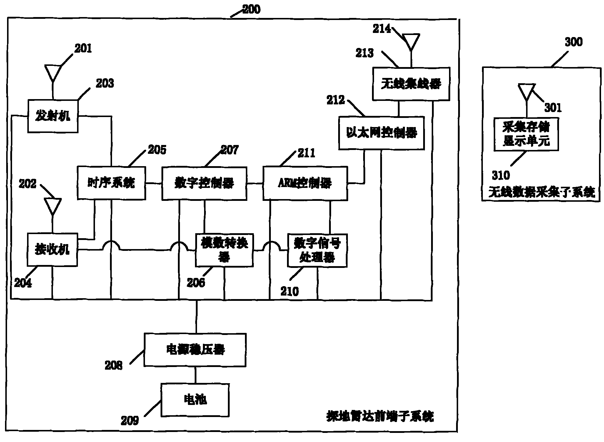
[0030] figure 2 It is a structural block diagram of the first embodiment of a wireless ground penetrating radar system of the present invention. The ground penetrating radar system includes a wireless data acquisition subsystem 300 and a ground penetrating radar front-end subsystem 200. The wireless data acquisition subsystem 300 is wirelessly connected to the ground penetrating radar front-end subsystem 200. The following is a specific description.

[0031] The wireless data collection subsystem 300 includes a collection, storage and display unit 310 and a first wireless transmitting and receiving antenna 301 connected to the collection, storage and display unit 310.

[0032] The ground penetrating radar front-end subsystem 200 includes a battery, a power regulator, a second wireless transmitting and recei...


PUM


Abstract

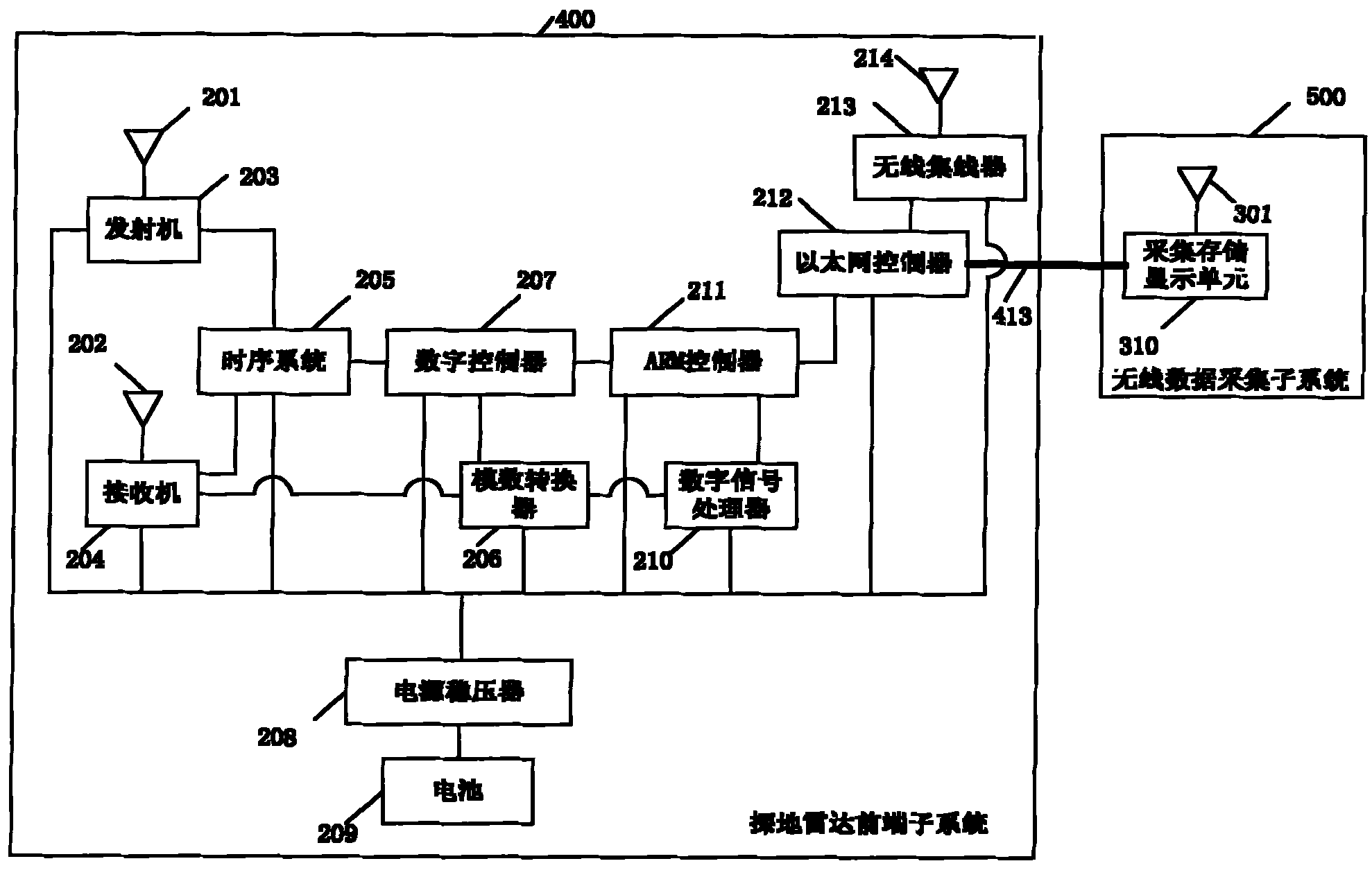
The invention relates to a wireless ground penetrating radar system, comprising a wireless data collection sub-system and a ground penetrating radar front end sub-system, wherein the wireless data collection sub-system comprises a collection and storage and display unit; the ground penetrating radar front end sub-system comprises a battery, a power supply manostat, an Ethernet controller, an ARM controller, a digital signal processor, an A / D converter, a digital controller, a sequential system, a transmitter, a transmitting antenna, a receiving antenna and a receiver; and the collection and storage and display unit and the Ethernet controller can be connected in a wireless / wired manner. The system is free of restriction of weight and volume as well as limitation of devices in the process of grounding scanning and ground distribution confirmation, and has less power consumption. No movement of the wireless data collection sub-system is needed.

Description

Technical field [0001] The invention relates to a ground penetrating radar (GPR) system with wireless data acquisition and automatic standby functions. Background technique [0002] Ground Penetrating Radar (GPR) system is a kind of geophysical exploration system, mainly used for shallow detection. It is currently a good instrument for underground non-destructive testing including highway structure testing. The areas include cavity inspection, road pavement or underground damage inspection, bridge deck layer positioning, underground pipeline inspection, bridge erosion detection near the river bed caused by bridge erosion, and other areas such as geophysical detection of geological sediments and geological structures, determination of bedrock And the depth of the groundwater level, the structure used to locate underground cultural relics (to prevent accidental damage) before excavation during archaeology, life detection and mine detection, etc. [0003] Traditional ground penetrati...

Claims


Application Information

Patent Timeline
IPC IPC(8): G01S13/89G01V3/00H04W84/12H04W88/12
CPCY02B60/50Y02D30/70
Inventor 刘策
Owner 武汉天毅达电子科技有限公司
Learn More