
Device and method for accurately positioning and tracking position of indicator on screen

A precise positioning and indicator technology, applied in installation, instrumentation, data processing input/output process, etc., can solve the problems of infrared matrix technology being susceptible to light interference, cost increase, and high cost

Inactive Publication Date: 2010-10-27
NANJING MAGON OPTO ELECTRICAL SCI & TECH
View PDF0 Cites 8 Cited by
  • Summary
  • Abstract
  • Description
  • Claims
  • Application Information

AI Technical Summary

Problems solved by technology

Both resistive film pressure sensing technology and electromagnetic induction technology require special whiteboards, and the cost increases with the increase of the board surface area, and damage to one area of ​​the board surface will affect the use of the entire whiteboard. Although some other technologies have nothing to do with the board, As long as the board is flat enough, generally speaking, the cost is relatively high, and there are some constraints that cannot be solved. For example, infrared matrix technology and photoelectric sensing technology are relatively easy to be interfered by light, and ultrasonic technology is easy to be affected by temperature.

Method used


Image

  • Device and method for accurately positioning and tracking position of indicator on screen
  • Device and method for accurately positioning and tracking position of indicator on screen
  • Device and method for accurately positioning and tracking position of indicator on screen

Examples


example 1

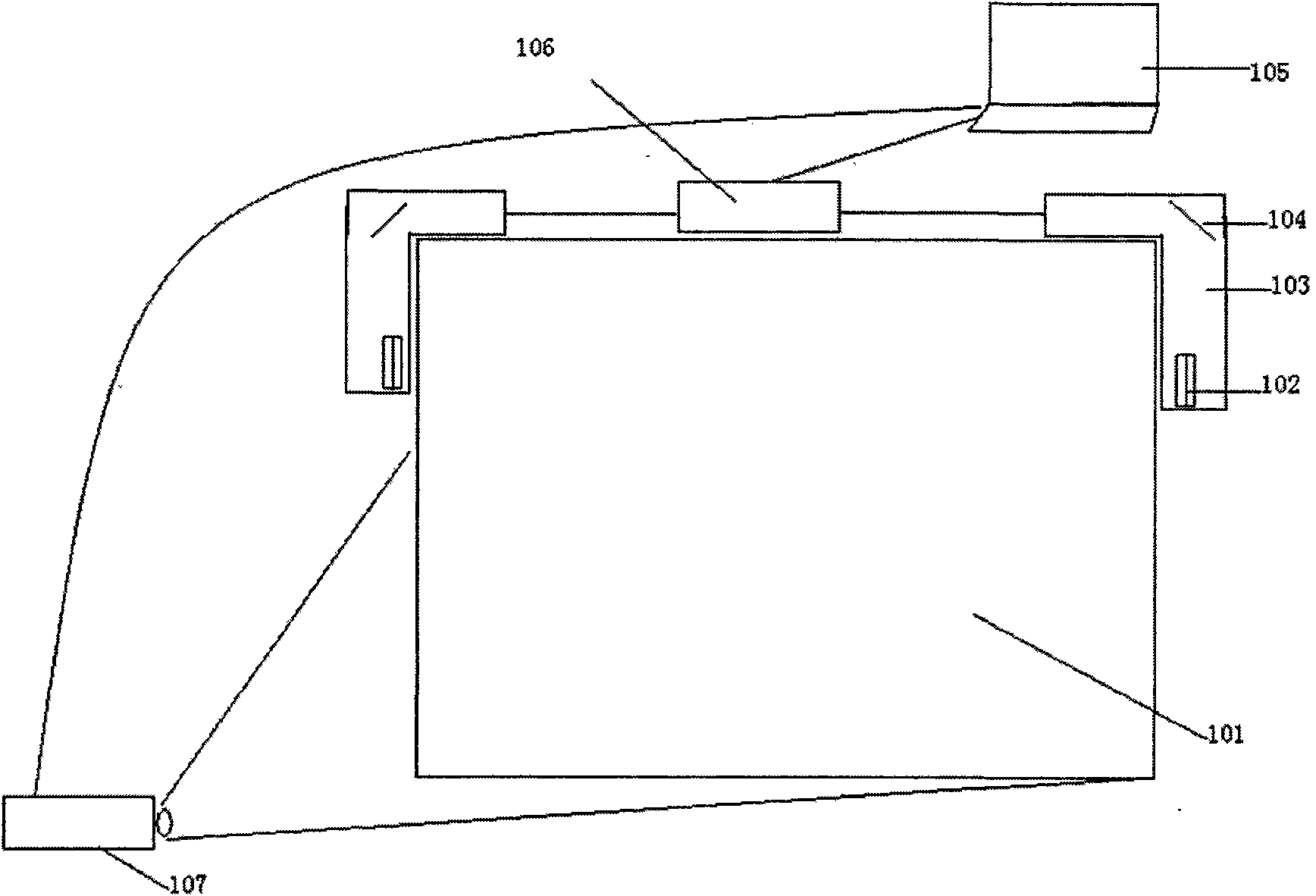
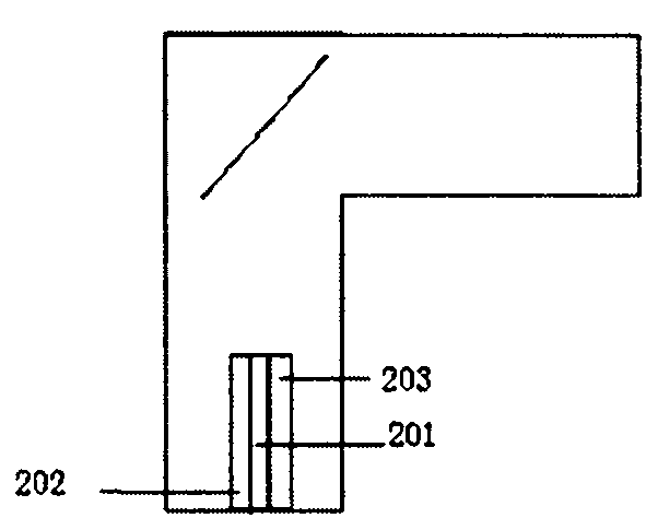
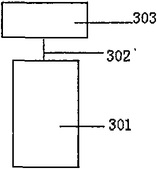
[0023] Such as figure 1 As shown, this example adopts a rectangular whiteboard 101, which is used to display the projection screen of the projector 107, and a signal receiving device 103 is respectively installed on the left and right upper corners of the whiteboard 101 to receive the signal sent by the luminous pen. In each signal receiving device, an infrared receiving diode 201 is adopted as a signal receiving device, and the signal receiving device is in a straight line with the motor shaft through the slit on the shading device, and an infrared light-emitting diode 202 is arranged at the same position as the infrared receiving diode 201, and a reflector 104 Installed on the shaft 302 of the motor 301, its center line coincides with the shaft of the motor, the signal receiving device 103 is connected with the signal processing device 106 and connected with the computer 105 through the computer USB interface, the luminescent pen 401 adopts infrared light, and the receiving d...

example 2

[0032] Such as figure 1 As shown, this example adopts a rectangular whiteboard 101, which is used to display the projection screen of the projector 107, and a signal receiving device 103 is respectively installed on the left and right upper corners of the whiteboard 101 to receive the signal sent by the luminous pen. Each signal receiving device adopts an infrared receiving diode 201 as a signal receiving device, and the signal receiving device is in a straight line with the motor shaft through the slit on the shading device, and an infrared light-emitting diode 202 and an infrared laser are arranged at the same position as the infrared receiving diode 201 203, the mirror 104 is installed on the shaft 302 of the motor 301, and its center line coincides with the shaft of the motor. The signal receiving device 103 is connected to the signal processing device 106 and connected to the computer 105 through the computer USB interface. The receiving diode 201 of the signal receiving d...


PUM


Abstract

The invention discloses a device and a method for accurately positioning and tracking the position of an indicator on a screen. The device comprises a luminous pen or a laser device, a light signal receiving device, a reflector, a motor, a signal processing module and a computer. The device is characterized in that the light signal receiving device comprises a light signal receiving diode, a light-emitting diode and a shading device; the reflector is connected with the motor and synchronously rotates along with a motor shaft; the signal receiving device is connected with the signal processing device and connected with the computer through a computer interface; the luminous pen produces bright light when contacting the screen; the laser device reflects laser emitted by the laser device to other indication equipment of a finger and the like through the reflector, and meanwhile the other indication equipment of the finger and the like transmit the reflection light of the laser to the receiving diode through the reflector; the light signal receiving device can be provided with a filter; and the light-emitting diode, the luminous pen and the laser device can emit light according to different frequencies.

Description

technical field [0001] The invention relates to a device and method for accurately locating and tracking the position of an indicator on a screen, and belongs to the field of computer man-machine interaction interface equipment. Background technique [0002] In the field of computer human-computer interaction, the electronic whiteboard is a revolutionary product that liberates the operator from the mouse and keyboard. At present, electronic whiteboard products are mainly realized by the following principles: resistive film pressure sensing technology, electromagnetic induction technology, infrared matrix technology, ultrasonic technology, CCD scanning technology and photoelectric sensing technology. Both resistive film pressure sensing technology and electromagnetic induction technology require special whiteboards, and the cost increases with the increase of the board surface area, and damage to one area of ​​the board surface will affect the use of the entire whiteboard. Al...

Claims


Application Information

Patent Timeline
Patent Type & Authority Applications(China)
IPC IPC(8): G06F3/042G02B7/182
Inventor 赵文龙
Owner NANJING MAGON OPTO ELECTRICAL SCI & TECH
Learn More