Network code divider and method for controlling front-end equipment

A technology of front-end equipment and code divider, which is applied in the direction of bus network, data exchange through path configuration, and closed-circuit television system. Drive ability and transmission distance, increase anti-interference ability, avoid the effect of engineering wiring

Active Publication Date: 2010-10-27
HANGZHOU HIKVISION DIGITAL TECH
View PDF5 Cites 7 Cited by
  • Summary
  • Abstract
  • Description
  • Claims
  • Application Information

AI Technical Summary

Problems solved by technology

[0005] 1. It is necessary to connect multiple such devices to realize communication, which increases the difficulty of engineering wiring and introduces some unnecessary interference signals;
[0006] 2. Once a cascade fails, the branch where the cascade is located will be invalid, and even affect the collapse of the entire system;
[0007] 3. The monitoring center cannot conduct unified real-time management of the front-end equipment connected to all levels of connectors, such as pan-tilts or ball cameras;
[0009] 1. Many monitoring devices are connected to one 485 bus. When there are many monitoring devices, the output power of one 485 interface is not enough, and the ball machine will be out of control or the ball machine will move around when it is not controlled.
[0010] 2. 485 bus wiring is basically divided into hand-in-hand mode and star mode. If it is connected in hand-in-hand mode, it will increase wiring troubles and maintenance difficulties, and it will easily lead to instability of bus communication
The star mode will have reflected signals, which will cause strong interference to communication
[0011] 3. Under the premise of an ideal environment, the transmission distance of the 485 bus can reach 1200 meters. Usually, the actual stable communication distance of the 485 bus is often not reached. This brings great difficulties to the engineering wiring when there are many front-end equipment and the area is relatively wide. big trouble

Method used


Image

  • Network code divider and method for controlling front-end equipment
  • Network code divider and method for controlling front-end equipment
  • Network code divider and method for controlling front-end equipment

Examples


Embodiment Construction

[0040] The following will clearly and completely describe the technical solutions in the embodiments of the present invention with reference to the accompanying drawings in the embodiments of the present invention. Obviously, the described embodiments are only some of the embodiments of the present invention, not all of them. Based on the embodiments of the present invention, all other embodiments obtained by persons of ordinary skill in the art without creative efforts fall within the protection scope of the present invention.

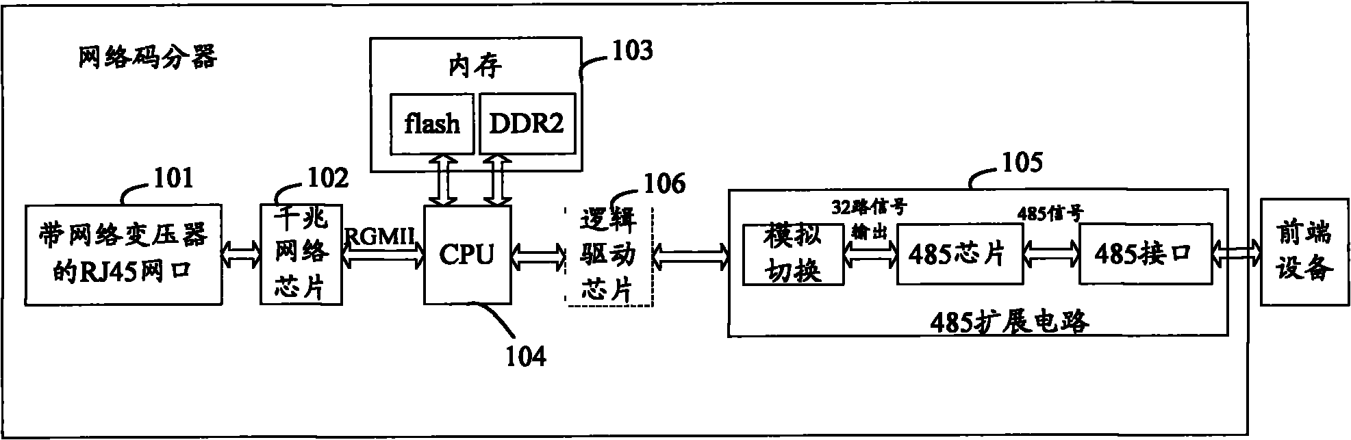
[0041] see figure 1 , which is a schematic structural diagram of a network code divider according to an embodiment of the present invention, specifically including:

[0042] The network port 101 is used to connect with the monitoring center through a network cable and receive a control command from the monitoring center, wherein the control command is a network signal, and the control command includes control object information and operation informati...


PUM


Abstract

The invention discloses a network code divider and a method for controlling front-end equipment. The network code divider comprises a network port, a network chip, a memory unit, a CPU and a 485 expander circuit, wherein the network port is used for connecting a monitoring center through a network cable and receiving a control command from the monitoring center; the network chip is used for converting the received network signals into second-type signals; the memory unit is used for storing applications and buffer data; the CPU is used for loading the applications from the memory when the network code divider is in power on reset so as to complete initialization operation, receiving the converted second-type signals, extracting control object information from the second-type signals and operating information indicated by the control command, and transmitting the control object information and the operating information to the 485 expander circuit; and the 485 expander circuit is used for controlling the front-end equipment corresponding to the control object information to execute the operation indicated by the control command. Through the network code divider, the monitoring center can perform data communication with the code divider through the network, and the centralized control of a plurality of pieces of front-end equipment is realized.

Description

technical field [0001] The invention relates to the technical field of video monitoring, in particular to a network code divider and a control method for front-end equipment. Background technique [0002] In the video surveillance industry such as traffic monitoring, it is necessary to collect and transmit video images to the monitoring center. For some important intersections or high-incidence points of traffic accidents, a monitoring point is generally set up every 500-1000 meters. Tables and ball machines monitor the road. However, the distance between the monitoring center and these monitoring points is several kilometers or even dozens of kilometers. Although the video image data can be transmitted to the monitoring center through the network, some control signals such as the control pan / tilt and dome camera cannot be transmitted such a long distance. Considering that the 485 interface can meet the complex system requirements, the monitoring center and the dome camera ...

Claims


Application Information

Patent Timeline
Patent Type & Authority Applications(China)
IPC IPC(8): H04L12/40H04N7/18
Inventor 邓宗玉姚建鑫钱学峰胡扬忠邬伟琪
Owner HANGZHOU HIKVISION DIGITAL TECH
Why Eureka
Try Eureka