Deposit preform injection moulding device with additional magnetic filed

A technology of spray forming and external magnetic field, applied in the field of metal billet processing, can solve the problems of low yield of atomized molten metal and large conical expansion angle, so as to improve the quality of forming, save manufacturing costs and improve economic benefits. Effect

Active Publication Date: 2010-11-03
BAOSHAN IRON & STEEL CO LTD
View PDF0 Cites 9 Cited by
  • Summary
  • Abstract
  • Description
  • Claims
  • Application Information

AI Technical Summary

Problems solved by technology

[0006] The technical problem to be solved by the present invention is to provide a spray forming device with an external magnetic field to solve the prob

Method used


Image

  • Deposit preform injection moulding device with additional magnetic filed
  • Deposit preform injection moulding device with additional magnetic filed
  • Deposit preform injection moulding device with additional magnetic filed

Examples


Example Embodiment

[0023] Example 1

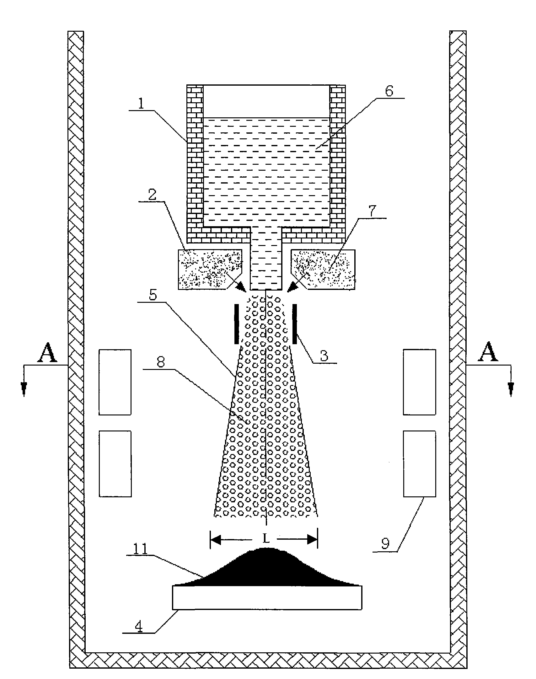
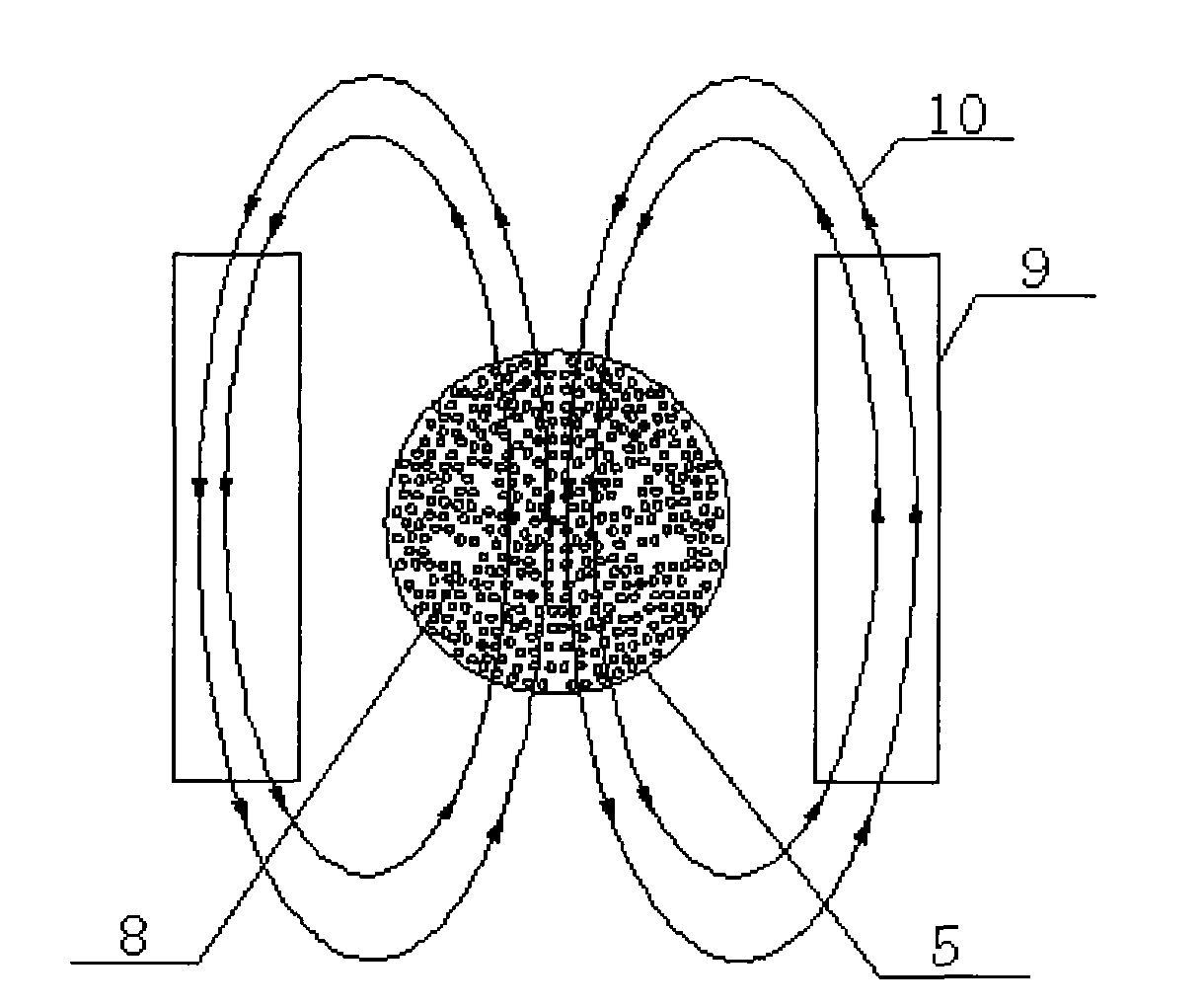
[0024] Such as figure 2 As shown, a deposition blank spray forming device with an external magnetic field includes a crucible 1, an atomizer 2, a charging electrode 3, and a depositor 4. The crucible 1 and the atomizer 2 are connected by a draft tube, The depositor 4 is located below the nozzle outlet of the atomizer, the atomized particle flight area 5 is between the atomizer nozzle and the depositor, the molten metal 6 is contained in the crucible 1, and the atomizer 2 contains high-pressure nitrogen 7, so The charging electrode 3 is located at the breaking point where the molten metal 6 is separated into atomized particles 8, a magnetic field generating device 9 is installed around the atomized particle flying area 5, and the magnetic field generating device is located below the charging electrode. The magnetic field generating device 9 is two energized electromagnetic coils arranged symmetrically on both sides of the atomized particle flight zone 5. The pl...

Example Embodiment

[0029] Example 2

[0030] A spray forming device for deposition blanks with an external magnetic field, comprising a crucible 1, an atomizer 2, a charging electrode 3, and a depositor 4. The crucible 1 and the atomizer 2 are connected by a draft tube, and the depositor 4 Located below the nozzle outlet of the atomizer, there is an atomized particle flight zone 5 between the atomizer nozzle and the depositor 4, the molten metal 6 is contained in the crucible 1, and the atomizer 2 contains high-pressure helium gas 7. The charging electrode 3 is located at the breaking point where the molten metal 6 is separated into the atomized particles 8. The atomized particle flight zone 5 is additionally provided with a toroidal magnetic field, and the axis of the magnetic field is the same as the axis of the atomized particle flight zone. See Figure 5 . When the charging electrode 3 is a positive electrode, the atomized particles 8 are negatively charged, and the direction of setting the an...


PUM


Abstract

The invention belongs to the field of metal blank processing, and particularly relates to a deposit preform injection moulding device. The deposit preform injection moulding device with an additional magnetic filed comprises a crucible (1), an atomizer (2), a charging electrode and a depositor (4); the crucible (1) and the atomizer (2) are communicated by a guide pipe; the depositor (4) is arranged below the outlet of the nozzle of the atomizer (2); an atomized grain flying region (5) is arranged between the nozzle of the atomizer (2) and the depositor (4); the charging electrode (3) is arranged at crushing sites where molten metal (6) is separated into the atomized grains (8); and a magnetic field generation device (9) is arranged around the atomized grain flying region (5) and under thecharging electrode. In the invention, the flying paths of the atomized grains can be changed to reduce the taper divergence angle of the atomized grain flying region by using an additional magnetic filed, thereby greatly improving the yield of the molten metal; and in addition, by changing the direction and magnitude of the magnetic filed, the moulding quality of deposit preform can be improved and the production cost of the deposit preform can be reduced, therefore, the economic benefits can be improved.

Description

technical field [0001] The invention belongs to the field of metal billet processing, in particular to a deposition billet spray forming device. Background technique [0002] Spray forming is an advanced material preparation technology developed on the basis of rapid solidification powder metallurgy technology. The outstanding advantage of the spray forming technology is that it combines the atomization and deposition forming of the metal melt into one, and can directly produce the final ingot with large size and rapid solidification characteristics from the liquid metal, which overcomes the various powder metallurgy technology processes, The serious problem of oxidation enables spray-deposited materials to have higher comprehensive mechanical properties than powder metallurgy materials. figure 1 A schematic diagram of the principle of spray forming is given. It uses the high-pressure inert gas 7 in the atomizer 2 to atomize the high-temperature molten steel 6 flowing out o...

Claims


Application Information

Patent Timeline
IPC IPC(8): B05B5/025B05B7/02B05B15/00
Inventor 樊俊飞袁锋任三兵赵顺利乐海荣
Owner BAOSHAN IRON & STEEL CO LTD
Why Eureka
Try Eureka