Induction and phase-shifting rectifier transformer

A rectifier transformer, transformer technology, applied in the direction of transformer/inductor coil/winding/connection, preventing/reducing unwanted electrical/magnetic influence, etc. Effects of wave loss, harmonic loss reduction, and harmonic magnetic flux reduction

Inactive Publication Date: 2010-11-03
HUNAN UNIV +2
View PDF1 Cites 12 Cited by
  • Summary
  • Abstract
  • Description
  • Claims
  • Application Information

AI Technical Summary

Problems solved by technology

[0003] In order to solve the technical problems of low efficiency and high noise of the traditional 12-pulse and multiple rectification system, the present invention provides an induction and phase-shifting rectifier transformer with high efficiency and low noise

Method used


Image

  • Induction and phase-shifting rectifier transformer
  • Induction and phase-shifting rectifier transformer
  • Induction and phase-shifting rectifier transformer

Examples


Embodiment Construction

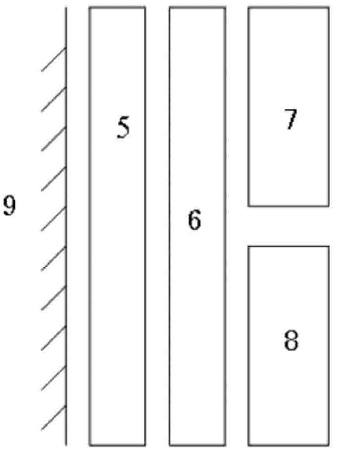
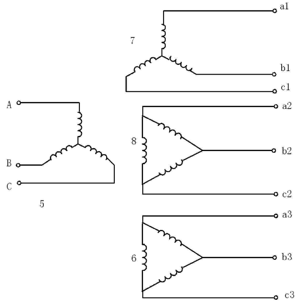
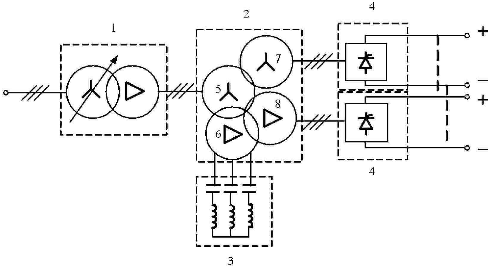
[0014] Such as figure 1 The induction and phase-shifting rectifier transformer 2 shown is a three-core column structure, and four windings are wound on each core column 9, which are the AC network side winding 5, the filter winding 6, and the valve side star connection winding 7. and delta connection winding 8; considering that the valve side of the rectifier transformer is mostly high current and low voltage, in order to facilitate heat dissipation; therefore, the grid side winding 5 is wound on the innermost layer, closest to the core; the filter winding 6 is wound on the grid side winding The outer layer of the outer layer; the star connection winding 7 and the delta connection winding 8 on the valve side are wound on the outer layer of the filter winding 6, and both adopt the same direction antiparallel winding method. The grid side winding 5 is connected to the voltage regulating transformer 1, the three-phase terminal leads of the filter winding 6 are connected to the 11...


PUM


Abstract

The invention discloses an induction and phase-shifting rectifier transformer. The transformer is in a three-pole iron core structure, wherein each iron core pole is wound by four windings which include an AC line side winding, a filter winding, a valve side star-connected winding and a valve side delta-connected winding; the line side winding is arranged in the innermost layer of each iron core pole; the filter winding is arranged on the external layer of the line side winding; and the valve side star-connected winding and the valve side delta-connected winding are arranged on the external layer of the filter winding and respectively connected with a group of six-pulse rectifiers. The invention can counteract harmonic magnetomotive force generated by 5, 7, 11, 13, 17 and 19 characteristic harmonic currents of the transformer, thereby ensuring that the current in the line side winding is basically in a sine wave mode and greatly reducing the harmonic loss of the line side winding and other AC line side power equipment.

Description

technical field [0001] The invention relates to a rectifying transformer, in particular to an induction and phase-shifting rectifying transformer. Background technique [0002] With the continuous development of my country's large-scale industrialization process, the capacity of rectification systems widely used in electrolysis, chemical industry, metallurgy and other industries is increasing, and these rectification systems mostly use nonlinear power electronic components such as thyristors or diodes. Electronic components will consume a large amount of reactive power during work and produce serious harmonic pollution. If effective harmonic control and reactive power compensation are not adopted, it will definitely bring serious harmonic pollution to the power system and affect the operation stability of the system. At present, in order to control harmonics and compensate reactive power, rectification systems in the above industries generally adopt two methods: (1) install ...

Claims


Application Information

Patent Timeline
Patent Type & Authority Applications(China)
IPC IPC(8): H01F27/28H01F27/34
Inventor 罗隆福许加柱张志文张勋奇李勇刘福生
Owner HUNAN UNIV
Why Eureka
Try Eureka