Rotating shaft clamping mechanism

A technology of rotating shafts and moving contacts, which is applied in the direction of contacts, electrical components, electric switches, etc., can solve the problems of high manufacturing and installation precision, poor operation reliability, and difficult manufacturing, and achieve high precision, easy reset, and easy processing The effect of easy molding

Inactive Publication Date: 2010-11-10
JIANGSU KAIFAN ELECTRICAL APPLIANCES
View PDF8 Cites 7 Cited by
  • Summary
  • Abstract
  • Description
  • Claims
  • Application Information

AI Technical Summary

Problems solved by technology

The existing rotating shaft clamping mechanism (such as US patent document US005313180A and Chinese patent 200610037996.9, etc.) usually sets a cam surface on the edge of the moving contact, and uses the positioning of the spring and the bayonet on the cam surface to realize the repelling of the moving contact. However, most of these structures have defects such as complex structure, high manufacturing difficulty, high manufacturing and installation precision requirements, and poor operational reliability.

Method used


Image

  • Rotating shaft clamping mechanism
  • Rotating shaft clamping mechanism
  • Rotating shaft clamping mechanism

Examples


Embodiment Construction

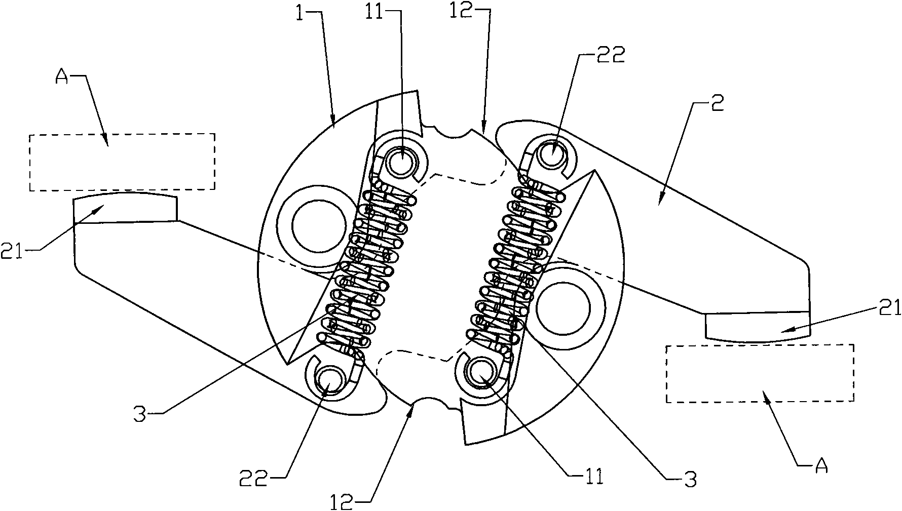
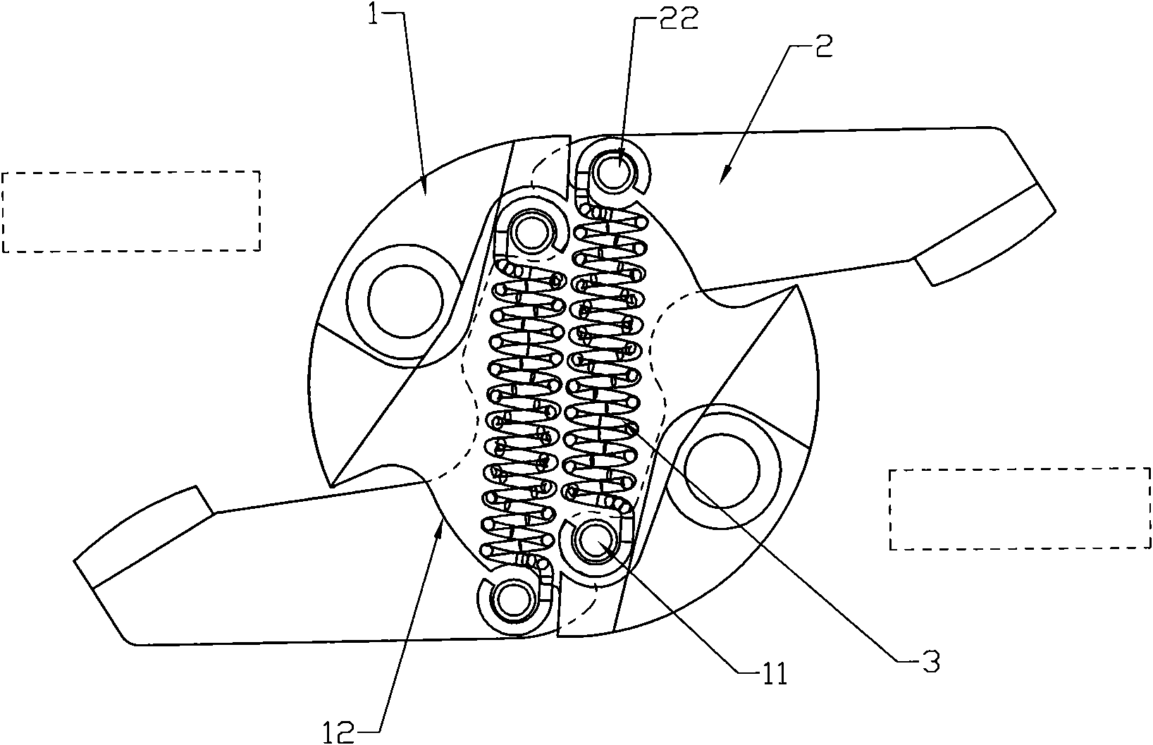
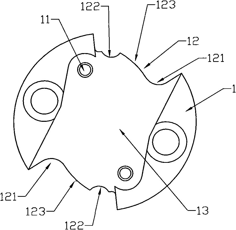
[0015] As shown in the figure, the rotating shaft clamping mechanism includes a rotating shaft body 1 and a movable contact 2 that runs through the inner cavity of the rotating shaft body and can rotate around the center of the rotating shaft body. , the movable contact 21 corresponding to the A contact of the lower two static contacts; the front and rear of the symmetrical center of the movable contact are each fixed with a bayonet 22 protruding to both sides, and each bayonet two ends are arranged by a pair of The extension spring 3 traction of the rotating shaft body outside, the fixed end of extension spring 3 is connected on the fixed pin 11 of rotating shaft body 1 outside both sides; It consists of two concave sections and an arched section in the middle, and the bayonet pin 11 always presses against the cam surface 12 under the force of the extension spring 3 . Both sides of the shaft body 1 are provided with grooves 13, and the extension spring 3 is located in the gro...


PUM


Abstract

The invention belongs to low-voltage electrical equipment, and relates to a rotating shaft clamping mechanism in a low-voltage circuit breaker. The rotating shaft clamping mechanism comprises a rotating shaft body and a moving contact terminal, wherein the moving contact terminal horizontally passes through an inner chamber of the rotating shaft body, can rotate around the centre of the rotating shaft body and is symmetrical about the centre; the front and rear ends of the moving contact terminal are provided with moving contacts corresponding to an upper fixed contact and a lower fixed contact on the circuit breaker respectively; the front and rear parts of the symmetrical centre of the moving contact terminal are fixed with a clamping pin extended out of the two sides respectively; the two ends of each clamping pin are towed by a pair of tension springs positioned outside the rotating shaft body; the fixed end of each tension spring is connected to corresponding fixed pins on the two outer sides of the rotating shaft body; the upper and lower edges of the rotating shaft body are provided with a section of cam surface respectively; each cam surface consists of two sunken sections and an arched section; the two sunken sections are positioned at the two ends of the cam surface, while the arched section is positioned on the middle part of the cam surface; and the clamping pins always cling to and are pressed on the corresponding cam surfaces under the action of the tension springs and can stay at the bottoms of the corresponding sunken sections. The rotating shaft clamping mechanism has the characteristics of simple structure, reliable motion and convenient manufacturing and mounting.

Description

technical field [0001] The invention belongs to low-voltage electrical equipment, and relates to a rotating shaft clamping mechanism in a low-voltage circuit breaker. Background technique [0002] The rotating shaft part of a low-voltage circuit breaker usually includes a rotating shaft body driven by a circuit breaker operating mechanism and a movable contact installed on the rotating shaft body. During normal operation, the rotating shaft drives the moving contact to rotate to realize the opening and closing of the static contact of the circuit breaker. However, when the circuit breaker is over-current due to a fault such as a short circuit, the contact needs to be disconnected quickly, and the use of It takes a long time for the protection circuit of the operating mechanism to drive the rotating shaft to perform the opening action. Therefore, in order to ensure that the contacts can be disconnected quickly during overcurrent, the rotating shaft parts of the existing stru...

Claims


Application Information

Patent Timeline
Patent Type & Authority Applications(China)
IPC IPC(8): H01H73/04H01H1/50
Inventor 王华章谭昌柏颜晨艳张金权
Owner JIANGSU KAIFAN ELECTRICAL APPLIANCES
Why Eureka
Try Eureka