Movable holder for silicon-based film solar cells
A technology of solar cells and movable fixtures is applied in the field of solar cells to achieve the effects of small access capacitance, large discharge area, and avoidance of inaccessible contact.
- Summary
- Abstract
- Description
- Claims
- Application Information
AI Technical Summary
Problems solved by technology
Method used
Image
Examples
Embodiment 1
[0035] The electrode plate is vertical, the feeding port of the cathode plate is triangular, and the feeding component is a cylinder.
[0036] The following is attached Figure 1-6 Specific embodiments of the present invention will be further described.
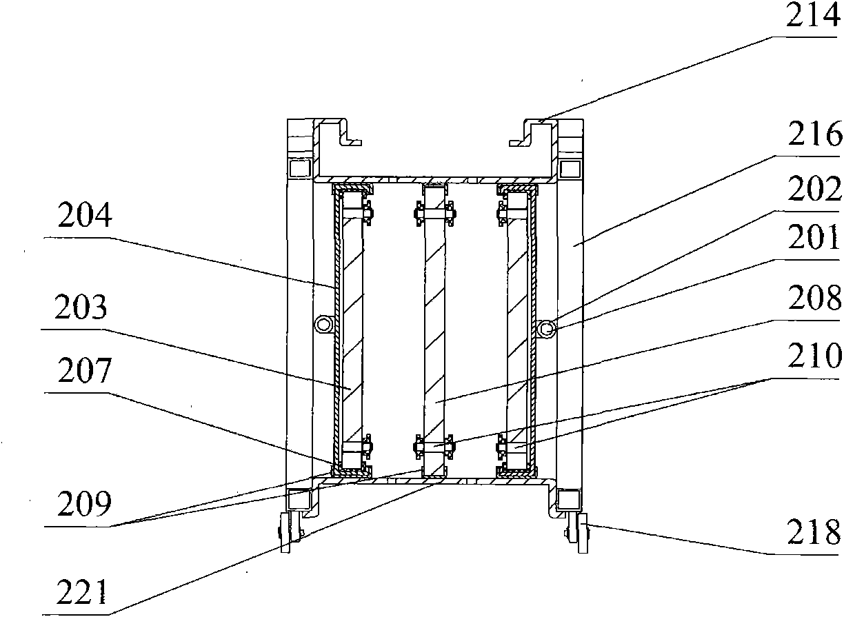
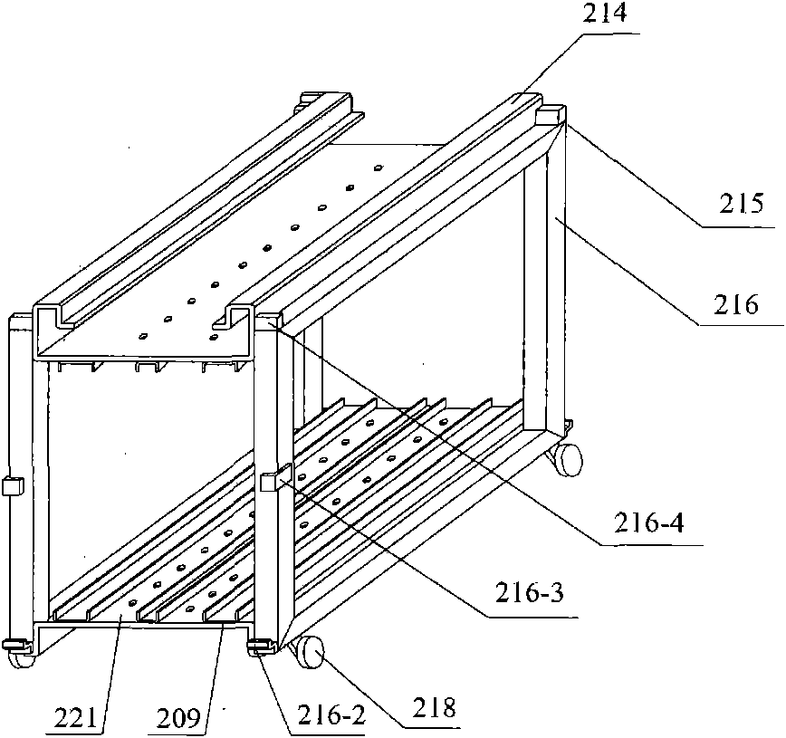
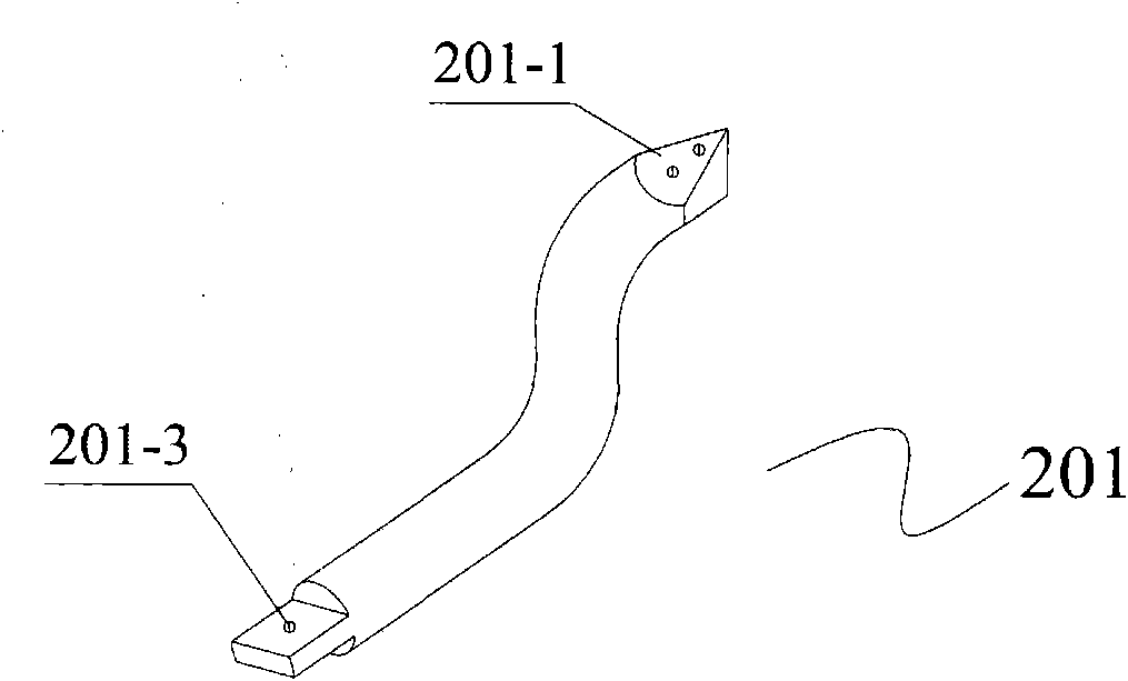
[0037] The movable fixture of the thin-film solar cell of the present invention uses a very high frequency power supply with an operating frequency (27.12-100MHz). Vacuum chamber 01 is used for realizing vacuum state, and gas system inlet 101 is arranged on it, power supply system inlet 102, vacuum system inlet 105, and the movable door that can open is installed in front of vacuum chamber 01. The fixture 02 is discharged in a vacuum environment, and the substrate 206 is deposited in a large-area uniform electric field chamber to deposit a p-i-n heterojunction laminated film to form a thin-film solar cell core board or chip, which is suitable for mass production. The upper inlet of the gas pipeline fixed on the fixture 02 i...
Embodiment 2
[0039] The feeding port of the cathode plate is a triangle, and the feeding component is a cylinder.
[0040] Figure 7 The fixture used is the same as in Example 1. In this embodiment, a vertical deposition chamber is adopted, and 12 pairs of electrodes are composed of 6 anode plates 208 and 12 cathode plates 203 , and the two cathode plates 203 share one anode plate 208 . 24 substrates 206 can be coated at the same time. Specific steps are as follows:
[0041] a) Place 24 glass substrates 206 (1640mm×707mm×3mm) with a 600nm thick transparent conductive film on 24 substrate positions in the jig 02, with the film facing outward and the glass facing the electrode plate.
[0042] b) Open the movable door of the vacuum chamber, push the jig 02 into the vacuum chamber 01 along the track 104, and close the movable door.
[0043] c) Vacuum to 5.0×10 -4 After Pa, argon gas was introduced, and when the pressure in the chamber reached 60Pa, the 40.68MHz VHF power supply was turned...
Embodiment 3
[0049] The electrode plate is vertical, the feed-in opening of the cathode plate is triangular, the feed-in component is a cylinder, and an anti-interference shielding device (not shown) is provided between the fixtures.
[0050] Figure 8 Use clamp with embodiment 1. In this embodiment, 6 fixtures 02 are used, and 24 substrates can be plated at the same time. Two cathode plates 203 in each fixture 02 share one anode plate 208 to form two pairs of electrodes, which can coat four substrates 206 at the same time.
[0051] a) Place 24 glass substrates 206 (1640mm×707mm×3mm) with a 600nm thick transparent conductive film on the substrate positions in 6 fixtures 02, with the film facing outward and the glass facing the electrode plate.
[0052] b) Open the movable door of the vacuum chamber, push the jig 02 into the vacuum chamber 01 along the track 104, and close the movable door of the vacuum chamber.
[0053] c) Vacuum to 5.0×10 -4 After Pa, argon gas was introduced. When th...
PUM
 Abstract
Description
Claims
Application Information
 - R&D
- Intellectual Property
- Life Sciences
- Materials
- Tech Scout
- Unparalleled Data Quality
- Higher Quality Content
- 60% Fewer Hallucinations
Browse by: Latest US Patents, China's latest patents, Technical Efficacy Thesaurus, Application Domain, Technology Topic, Popular Technical Reports.
© 2025 PatSnap. All rights reserved.Legal|Privacy policy|Modern Slavery Act Transparency Statement|Sitemap|About US| Contact US: help@patsnap.com


