Supercharge Your Innovation With Domain-Expert AI Agents!

Crank of pumping unit

An oil pumping unit and crank technology is applied in the field of improving the crank structure of the oil pumping unit, which can solve the problems of heavy design, and achieve the effects of reducing the overall weight, improving the manufacturability, and reducing the cost.

Inactive Publication Date: 2010-11-17
JIANGSU SINOPETRO SUPERBSKILL MACHINE
View PDF0 Cites 0 Cited by
  • Summary
  • Abstract
  • Description
  • Claims
  • Application Information

AI Technical Summary

Problems solved by technology

The crank on the pumping unit in the prior art has always been designed to be relatively heavy in order to meet the above dynamic mechanical properties and provide sufficient balance torque, such as figure 2 As shown, the whole is a flat plate

Method used


Image

  • Crank of pumping unit
  • Crank of pumping unit
  • Crank of pumping unit

Examples


Embodiment Construction

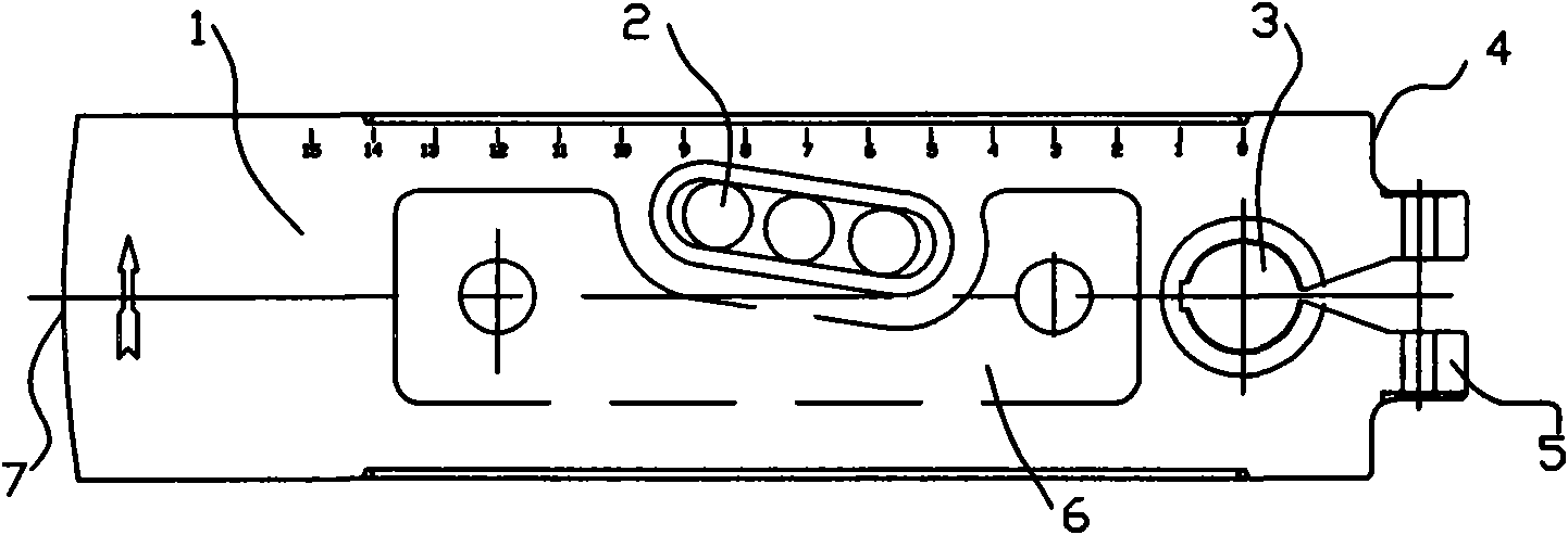
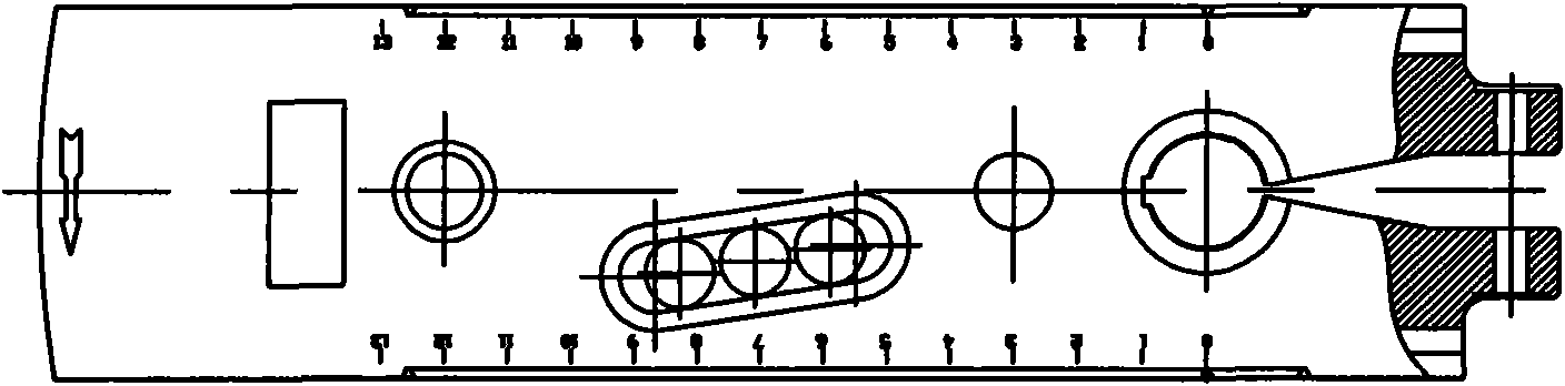
[0011] The invention as figure 1 As shown, the top end of the crank body 1 is provided with a shaft hole 3 for connecting the drive shaft, the middle part of the crank body 1 is provided with a connecting hole 2 for connecting the living hinge to the connecting rod of the pumping unit, and the middle part of the crank body 1 is provided with a groove 6, so that The thickness is reduced and the weight is reduced. The distance between the tail end 7 of the crank body 1 and the shaft hole 3 is lengthened, and the thickness of the tail end 7 is thickened, and the distance between the top edge 4 of the crank body 1 and the shaft hole 3 is shortened. The volume formed by lengthening and thickening is smaller than the volume formed by thinning and shortening.

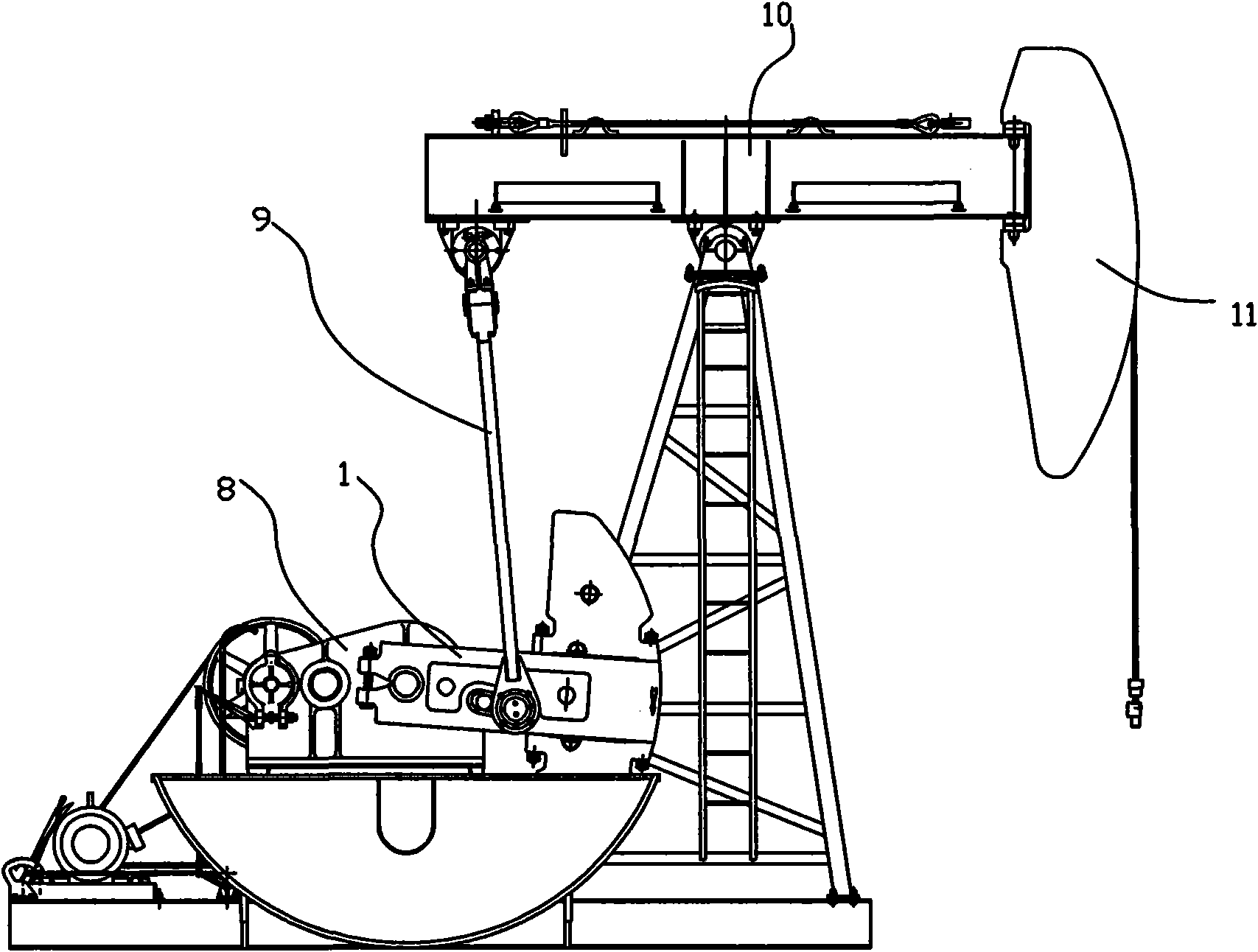
[0012] When applying the present invention, the lengthening of the tail end 7 will adapt to the profile of the pumping unit shield, and it can be lengthened as much as possible when space permits. When the amount of lengthen...


PUM


Abstract

The invention relates to a crank of a pumping unit, in particular to a driving crank of a pumping unit connecting rod. A shaft hole for connecting a driving shaft is formed at the top end closed to a crank body; and a connection hole for hinging the pumping unit connecting rod movably is formed in the middle part of the crank body. The crank is characterized in that the thickness of the middle part of the crank body is reduced; and the distance between the tail end of the crank body and the shaft hole is lengthened, the thickness of the tail end is thickened, and the distance between the top end edge of the crank body and the shaft hole is shortened. In the crank of the pumping unit, the manufacturability of a casting structure of the crank body is improved, the total weight is reduced, the cost is reduced, and the balancing effect is improved.

Description

technical field [0001] The invention relates to a driving crank of a connecting rod of an oil pumping unit, in particular to an improvement on the structure of the upper crank of the oil pumping unit. Background technique [0002] Currently, pumping units (such as image 3 As shown), the working process is as follows: the driving mechanism 8 drives the crank 1 to rotate, and the lower end of the connecting rod 9 is hinged at the middle part of the crank 1. When the crank 1 rotates, the middle hinge point moves along a circle, and the lower end of the connecting rod 9 is driven to be in the middle of the circle. Upward movement, the upper end of the connecting rod 9 is hinged to one end of the beam 10, and the middle part of the beam 10 is hinged on the support, and the upper end of the connecting rod 9 drives the beam 10 to swing, and then drives the donkey head at the other end of the beam 10 to do " Kowtow" action. As a transmission link in the above work, the crank shoul...

Claims


Application Information

Patent Timeline
Patent Type & Authority Applications(China)
IPC IPC(8): E21B43/00
Inventor 俞步阳顾建平
Owner JIANGSU SINOPETRO SUPERBSKILL MACHINE
Features
  • R&D
  • Intellectual Property
  • Life Sciences
  • Materials
  • Tech Scout
  • Unparalleled Data Quality
  • Higher Quality Content
  • 60% Fewer Hallucinations
Learn More