Method and device for heating flowing fluid as well as heating equipment applying same

A technology of flowing fluid and heating equipment, which is applied to fluid heaters, lighting and heating equipment, coil devices, etc., can solve the problems of high energy consumption, easy damage, and low thermal efficiency of the devices, and achieve long service life, fast heating speed, The effect of high thermal efficiency

Active Publication Date: 2010-11-17
佛山市南海超豪五金配件有限公司
View PDF0 Cites 13 Cited by
  • Summary
  • Abstract
  • Description
  • Claims
  • Application Information

AI Technical Summary

Problems solved by technology

Direct combustion of coal, diesel, heavy oil, firewood and other fuels in ordinary kilns has low thermal efficiency and serious pollution
In order to achieve energy saving and environmental protection, some electric heating wires are used as heating elements. This type of device also consumes a lot of energy. Usually, the power of each electric heating wire is 6-10KW, and sometimes the total...

Method used


Image

  • Method and device for heating flowing fluid as well as heating equipment applying same
  • Method and device for heating flowing fluid as well as heating equipment applying same
  • Method and device for heating flowing fluid as well as heating equipment applying same

Examples


Embodiment 1

[0032] An electric heating device.

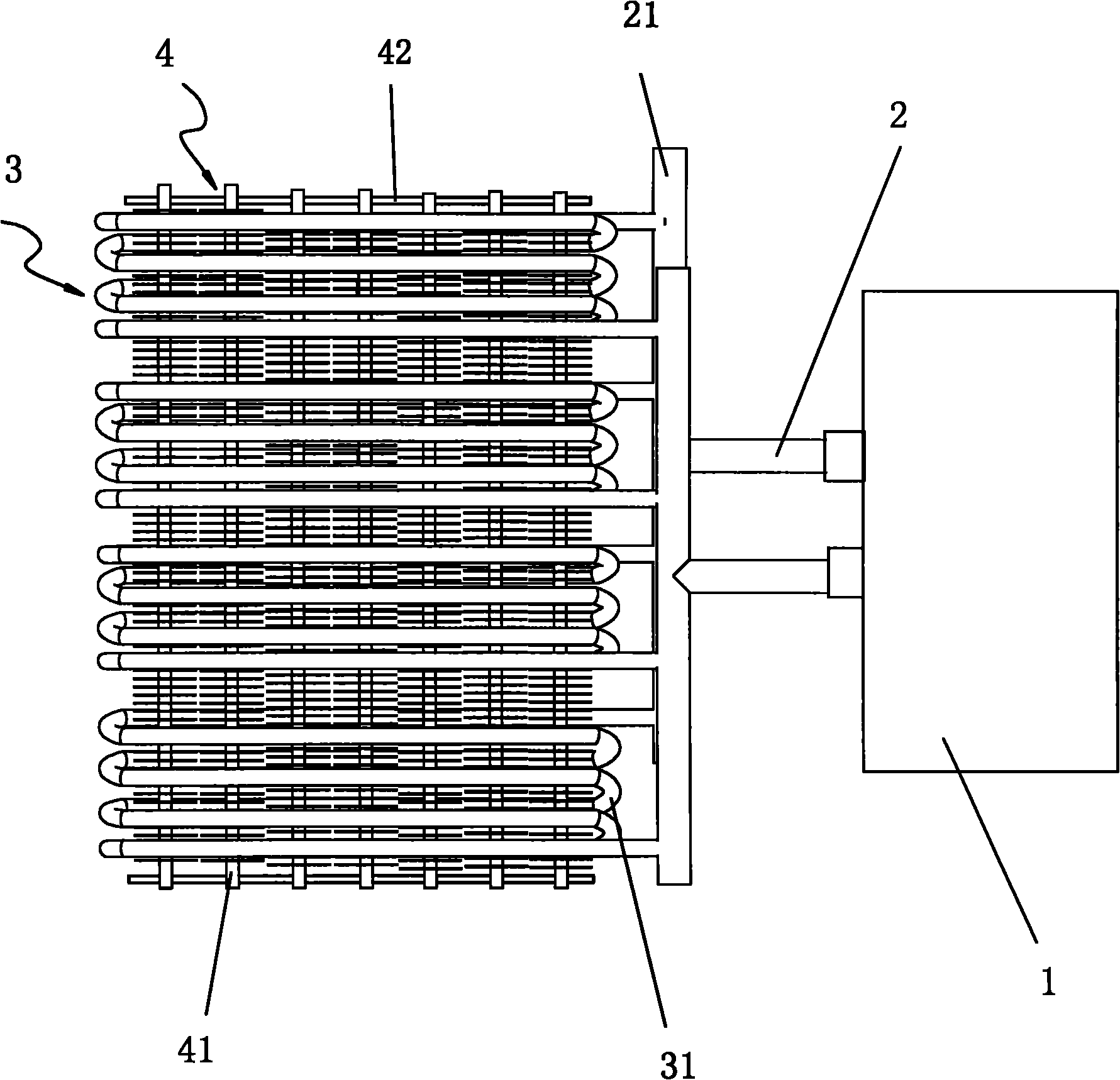
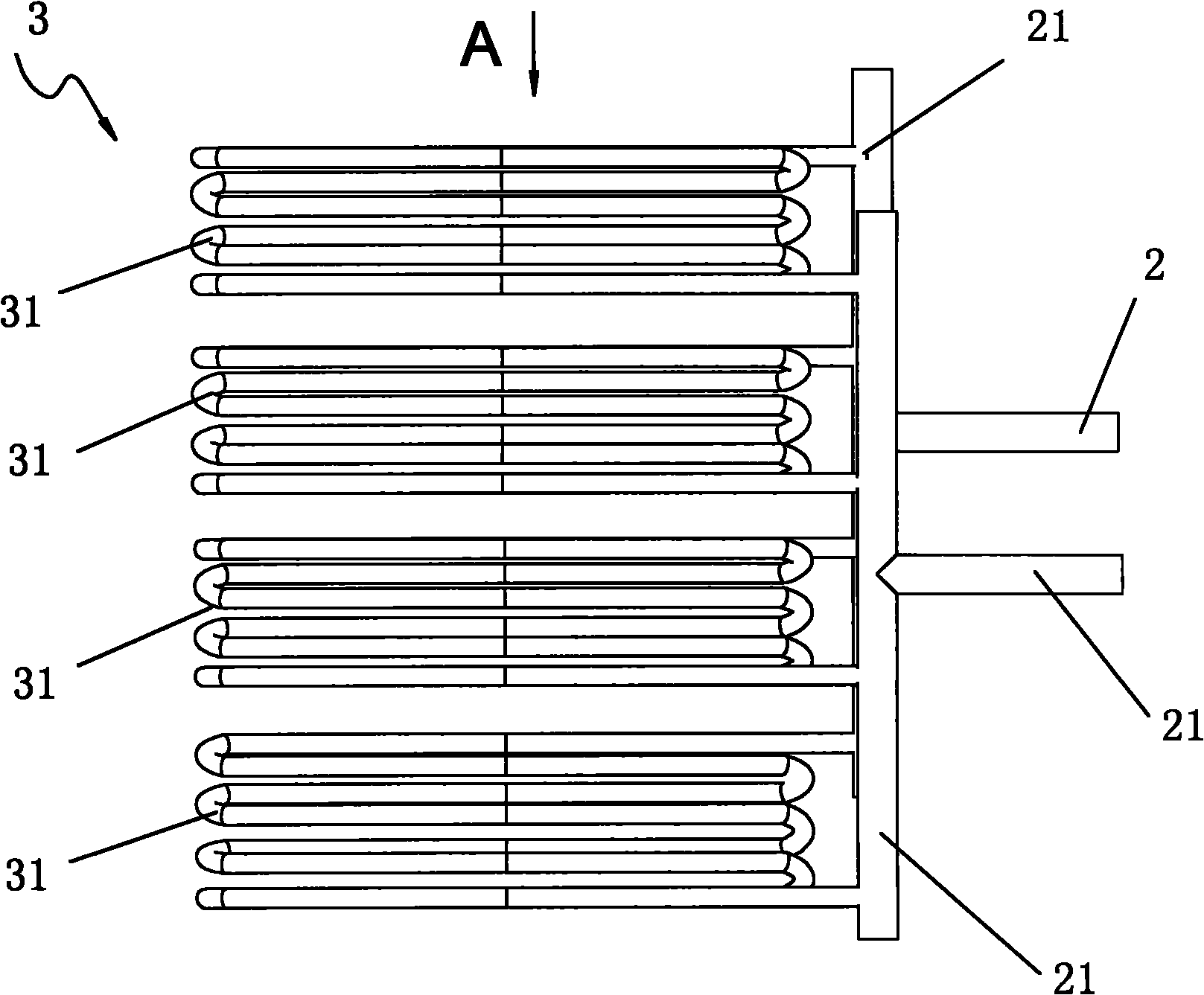
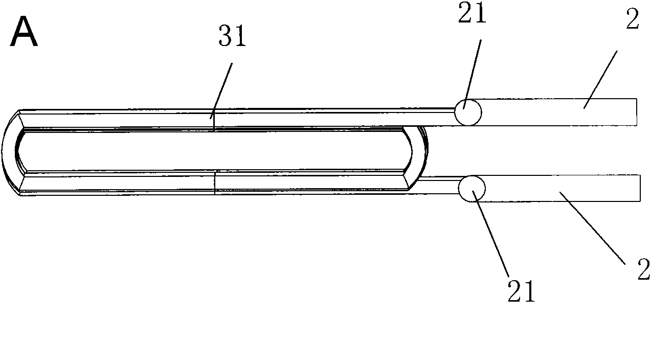
[0033] see Figure 1-3 The two high-frequency output terminals 2 of the high-frequency furnace are respectively connected to two conductive connecting rods 21 that are parallel to each other (or roughly parallel), and the high-frequency induction coil 3 is composed of several unit induction coils 31, and each unit induces The coil is provided with several coils of induction coils, and its two ends are electrically connected to two parallel conductive connecting rods 21, so that the unit induction coil is connected between the two conductive connecting rods, and the high-frequency induction coil 3 is formed in parallel. A metal induction body 4 electrically isolated from the induction coil is fixed in the cavity connected with the inner cavity in a straight line.

[0034] Usually, each unit induction coil 31 can be provided with 3-5 coils respectively, and the number of high-frequency induction coils should match the number of transformer c...

Embodiment 2

[0039] An electric heating device.

[0040] see Figure 7-8 The difference from Embodiment 1 is that in this example, each unit induction coil 31 forming the high-frequency induction coil 3 is a single-turn U-shaped coil body, and the U-shaped coil bodies are equidistantly spaced and arranged along the direction of the conductive connecting rod 21 , the two ends of each U-shaped coil body 31 are electrically connected with two conductive connecting rods 21 respectively, and are connected between the two conductive connecting rods. of).

Embodiment 3

[0042] An electric heating device.

[0043] see Figure 9 , Figure 10 , different from Embodiment 1, the cross-section of the cavity surrounded by the high-frequency induction coil 3 in this example is circular, and the metal induction body 4 is arranged in a cylindrical shape by a number of surrounding circular cavities. There are hollow or solid metal rods 41 with gaps between them. Both ends of each metal rod 41 are relatively fixed to the ring-shaped fixing strips 42 located at the longitudinal ends of the high-frequency induction coil.


PUM


Abstract

The invention relates to a method and a device for heating flowing fluid as well as heating equipment applying the same. In the method, a high-frequency induction coil is connected with a high-frequency power output end; the high-frequency induction coil is internally provided with a metal inductor electrically insulated with the high-frequency induction coil; and the high-frequency induction coil internally provided with the metal inductor is arranged in the flowing fluid and is used for heating the flowing fluid. The flowing fluid is heated by adopting the device of the invention, the invention has the advantages of energy saving, environment protection, high thermal efficiency, no pollution, low energy consumption, high heating speed and long service life. Because the flowing fluid medium can play a role of continuously cooling the metal inductor and the induction coil of a heating source, the heating device is kept a working state of long-term continuous heating.

Description

technical field [0001] The invention belongs to a heating method and device, in particular to a method and device for heating flowing fluid and heating equipment using the same. Background technique [0002] Traditional devices for generating hot air, hot water or steam use coal, diesel oil, heavy oil or even firewood as heat sources. The burning of the above fuels heats the flowing liquid and gas to generate hot air, hot water or steam. The direct combustion of coal, diesel, heavy oil, firewood and other fuels in ordinary kilns has low thermal efficiency and serious pollution. In order to achieve energy saving and environmental protection, some electric heating wires are used as heating elements. This type of device also consumes a lot of energy. Usually, the power of each electric heating wire is 6-10KW, and sometimes the total power must reach 150KW before it can be applied to the hot air for drying. Furnaces or steam furnaces for other purposes, while the thermal effici...

Claims


Application Information

Patent Timeline
IPC IPC(8): F24H1/10F24H3/04F22B1/28F22B9/18H05B6/36
Inventor 梁信辉李建华
Owner 佛山市南海超豪五金配件有限公司
Why Eureka
Try Eureka