
Slope rill erosion measurer

A technology for measuring instruments and slopes, applied in measuring devices, measuring inclinations, mechanical measuring devices, etc., can solve the problems of expensive instruments, large amount of data acquisition, long measurement time, etc., and achieve improved measurement accuracy and simple data processing , easy to carry effect

Inactive Publication Date: 2012-05-23
BEIJING FORESTRY UNIVERSITY
View PDF0 Cites 0 Cited by
  • Summary
  • Abstract
  • Description
  • Claims
  • Application Information

AI Technical Summary

Problems solved by technology

[0003] In the above-mentioned prior art, the first type of instrument is easy to operate and easy to master, but there are problems such as low measurement accuracy or long time-consuming application in monitoring, which easily disturbs the ground surface and affects the measurement results, and the topographic needle board is mostly used for indoor soil. Erosion simulation tests have a limited scope of use; although the measurement accuracy of the second type of instrument has been improved, the resolution of GPS to measure the micro-topographic changes of the slope is still limited, and the amount of data acquisition is large, the measurement time is long, and the later data processing is relatively difficult. Complicated; the third type of instrument has the highest accuracy compared with the first two types, and can intuitively reflect the erosion pattern of rills, but the instrument is expensive, the control point setting is troublesome, and the operation technology is difficult to master, so it is difficult to be popularized in actual work

Method used


Image

  • Slope rill erosion measurer
  • Slope rill erosion measurer
  • Slope rill erosion measurer

Examples


specific Embodiment approach

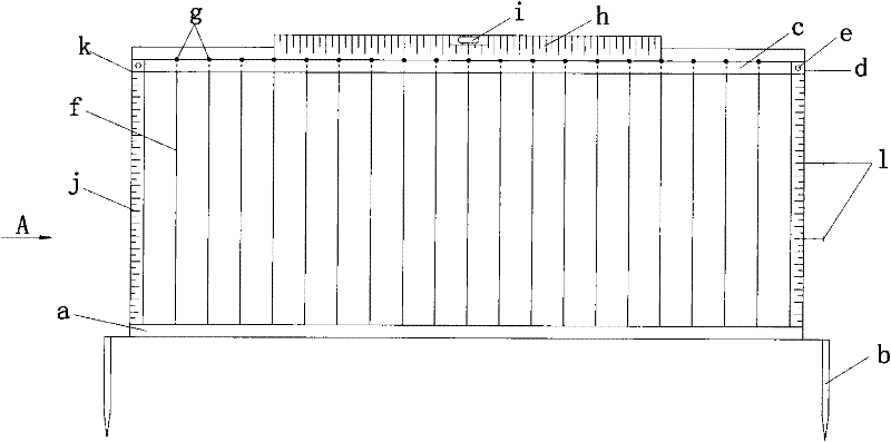
[0032] exist figure 1 and figure 2 Among them, the aluminum alloy frame (a) is the main body of the slope surface gully erosion measuring instrument, the fixing braze (b) is connected to its bottom through the fixing screw (n), inserted into the slope surface to fix the measuring instrument, and the two ends of the sliding beam (c) have The clamp (d) is set on the aluminum alloy frame (a) and can slide up and down. By adjusting the elastic screw (e) above, the sliding crossbeam can be fixed at any position on the frame. The upper end of the stylus (f) is connected with a nut (g), and the lower end passes through the sliding beam and is inserted into the frame. A horizontal scale (h) and a level (i) are connected to the upper end of the frame, a protractor (k) and a vertical scale (j) are connected to the left side, and there is a freely rotating pointer (m) at the center of the protractor. There are two set bolts (l) on the right side of the frame to which another gauge can...


PUM


Abstract

The invention discloses a slope rill erosion measurer which is characterized in that a transverse beam which can slide up and down is connected with a metal framework; one end of a measuring needle is provided with a screw cap, and the other end of the measuring needle passes through the transverse beam and then extends out of the framework; the upper end of the framework is provided with a levelinstrument and a transverse scale, and the lower end of the framework is connected with two fixed borers which can be inserted into a slope; one side of the framework is provided with a vertical scale and an angle gauge, and the other side of the framework is connected with two positioning bolts; and the slope rill erosion measurer can be connected with another measurer in parallel for use. When the measurer is vertically inserted into the slope, the measuring needle is used for measuring the amount of rill erosion of soil of the slope, and the angle gauge is used for measuring the gradient of the slope. The slope rill erosion measurer is suitable for measuring the amount of slope rill erosion in field soil, has the advantages of simple operation and convenient carrying, and can be assembled and disassembled on the spot; a digital photographic technology can be used for quickly recording the measured data, thereby improving the measuring accuracy; and the data processing at the later stage is relatively simple.

Description

technical field [0001] The invention relates to a measuring device for soil surface erosion and rill erosion on bare or covered soil slopes, in particular to a measuring device capable of measuring slope gradient and slope gully erosion. Background technique [0002] At present, there are mainly three types of devices commonly used to measure soil erosion on slopes: the first type is a measuring ruler and a topographic needle board. Calculate the amount of rill erosion according to the trapezoidal section. The latter is to use the paper coordinate system on the stylus to record the elevation value of the rill section, and use WindowsSurfer software to generate a three-dimensional model of the rill and calculate the soil erosion at the same time; The second type is GPS, using GPS-RTK real-time dynamic measurement, using ArcGIS software to generate the spatial distribution model of slope rill erosion form, and calculating the amount of gully erosion; the third type is 3D laser...

Claims


Application Information

Patent Timeline
Patent Type & Authority Patents(China)
IPC IPC(8): G01B5/00G01C9/12
Inventor 杨建英石丽丽赵廷宁赵强赵方莹韩煜杨剑宾王福常骆汉齐锋高俊关枫
Owner BEIJING FORESTRY UNIVERSITY
Learn More