
Source driver

A source driver and multiplexer technology, applied to instruments, static indicators, etc., can solve the problems of reducing the efficiency of the source driver, electromagnetic interference of the source driver 106, abnormal operation of the liquid crystal display, etc., and achieve the effect of reducing electromagnetic interference

Inactive Publication Date: 2010-11-17
HIMAX TECH LTD
View PDF0 Cites 22 Cited by
  • Summary
  • Abstract
  • Description
  • Claims
  • Application Information

AI Technical Summary

Problems solved by technology

At present, without considering the influence of line loading on signal transmission, since the output multiplexers controlled by the control signal are simultaneously enabled to output the driving voltage, an instantaneous large current will be generated, which will cause the source Electromagnetic Interference in Driver 106
Electromagnetic interference will reduce the performance of the source driver 106, which will cause abnormal operation of the liquid crystal display. Therefore, the source driver must solve the above problems through circuit design.

Method used


Image

  • Source driver
  • Source driver
  • Source driver

Examples


Embodiment Construction

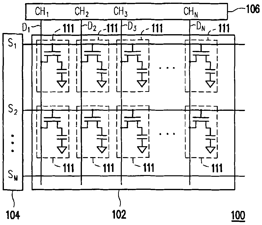
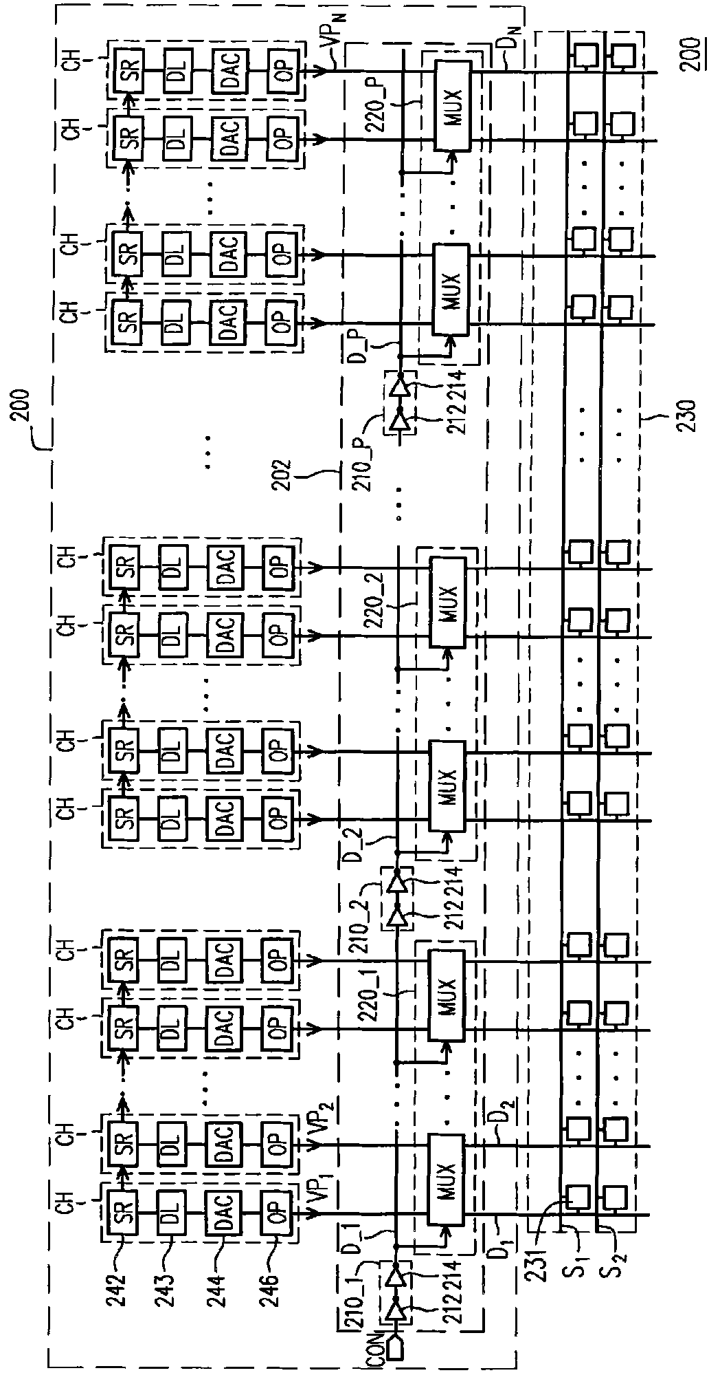
[0017] Generally speaking, the source driver includes a plurality of driving channels to respectively drive the pixels on each data line in different scanning periods. Each driving channel of the source driver may include a shift register (shift register, SR), a digital-to-analog converter (digital-to-analog converter, DAC), an output buffer (output buffer) and the like. The shift register controls a data latch (data latch, DL) to receive video data (video data) according to a timing control signal. A digital-to-analog converter converts the video data to an analog voltage, and an output buffer is used to boost this analog voltage. In addition, the back-end circuit of the source driver further includes a plurality of output multiplexers, which simultaneously transmit the analog voltage of the driving channel to the pixels on the display panel according to the control signal, wherein the control signal is, for example, controlled by a timing controller. produce. In order to s...


PUM


Abstract

The invention discloses a source driver, which is used for driving a display panel. The source driver comprises a plurality of channels and an output switch, wherein the channels generate a plurality of drive voltages; the output switch is coupled with the channels and selectively connects the channels to a plurality of data wires of the display panel; the data wires comprise a plurality of odd data wires and a plurality of even data wires; the output switch comprises a plurality of output multiplexers; each output multiplexer is coupled with the corresponding channels, and connects at least one corresponding channel to one of the plurality of data wires when enabled; and the output multiplexers are sequentially enabled in a frame period.

Description

technical field [0001] The present invention relates to a source driver, in particular to a source driver for reducing electromagnetic interference (EMI). Background technique [0002] Since liquid crystal displays (liquid crystal displays, LCDs) have the advantages of light weight, small size, low power consumption, and no radiation scattering, they have been widely used in recent years. [0003] figure 1 A schematic diagram of a conventional liquid crystal display. like figure 1 As shown, the liquid crystal display 100 includes a display panel 102 , a gate driver 104 and a source driver 106 . The display panel 102 includes a pixel array composed of a plurality of pixels 111 . The gate driver 104 sequentially enables the scan lines S1 to SM. Next, the source driver 106 converts the digital video data into a plurality of driving voltages, and transmits the plurality of driving voltages to the pixels 111 on the enabled scan lines through the data lines D1-DN to display i...

Claims


Application Information

Patent Timeline
IPC IPC(8): G09G3/20G09G3/36
Inventor 黄大容陈建儒
Owner HIMAX TECH LTD
Features
  • Generate Ideas
  • Intellectual Property
  • Life Sciences
  • Materials
  • Tech Scout
  • Unparalleled Data Quality
  • Higher Quality Content
  • 60% Fewer Hallucinations
Learn More