Direct-drive switched reluctance planar motor
A switched reluctance, planar motor technology, used in electrical components, electromechanical devices, electric components, etc., can solve problems such as stability, speed and accuracy limitations, movement limitations of mover gantry, lack of self-starting ability, etc. The effect of reducing weight, improving motion control accuracy, and saving materials
Inactive Publication Date: 2010-11-17
TAIYUAN UNIV OF TECH
View PDF1 Cites 8 Cited by
- Summary
- Abstract
- Description
- Claims
- Application Information
AI Technical Summary
Problems solved by technology
However, the superposition of linear motors to form planar motion devices has not fundamentally broken away from the mode of "low-dimensional motion mechanisms are superimposed to form high-dimensional motion mechanisms", especially for the bottom linear motors that need to carry the upper layer linear motors and related mechanical components Weight, stability, speed and accuracy are all limited
The existing switched reluctance planar motors do not have self-starting capability in the x direction due to the different arrangement of the movers in the x and y directions, and the movement of the mover gantry is limited by the position
Method used
View moreImage
Smart ImageViewing Examples

Examples
Embodiment approach 1
[0028] Embodiment 2
Embodiment approach 2
[0030] Embodiment 3
Embodiment approach 3
Login to View More PUM
 Abstract
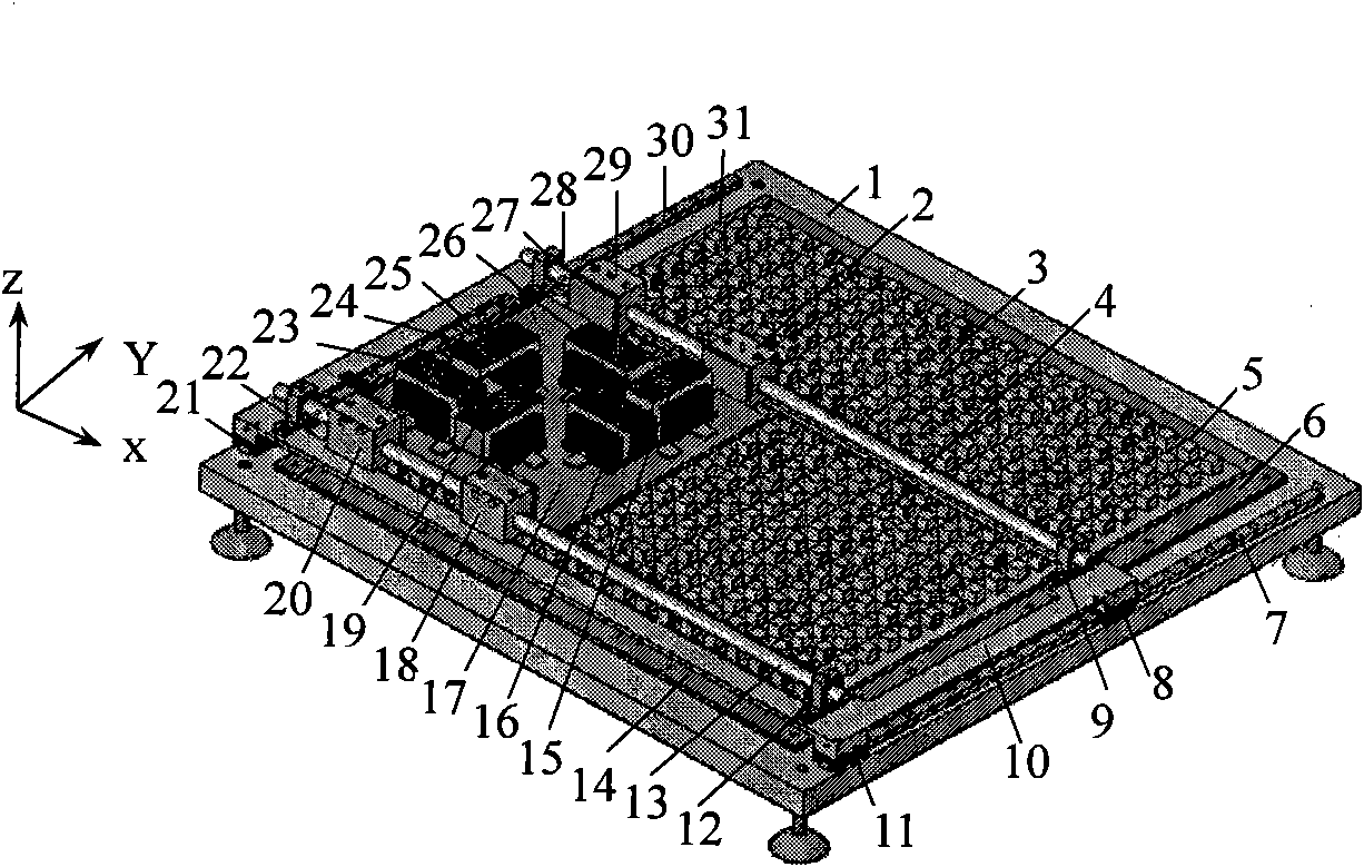
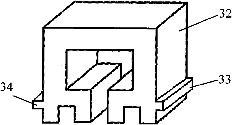
The invention discloses a direct-drive switched reluctance planar motor, which belongs to the field of electromechanical research. The motor is characterized in that a right lug boss 33 and a left lug boss 34 are arranged on the two sides of a rotor core 32 and matched with a rotor buckle to fix an XA-phase rotor 24, an XB-phase rotor 19, an XC-phase rotor 15, a YA-phase rotor 23, a YB-phase rotor 16 and a YC-phase rotor 26 on a rotor rack 17; the height of the rotor buckle is 0.3 to 0.5mm less than those of the right lug boss 33 and the left lug boss 34; a first right connecting plate 36, a second right connecting plate 37, a first left connecting plate 38 and a second left connecting plate 39 are arranged on the two sides of a rotor rack plate 35; on one hand, the first right connecting plate 36, the second right connecting plate 37, the first left connecting plate 38 and the second left connecting plate 39 are fixedly connected with the rotor rack plate 35; on the other hand, the connecting plates are also fixedly connected with a first straight bearing 29, a second straight bearing 2, a third straight bearing 18 and a fourth straight bearing 20; and thus the rotor rack 17 can flexibly move along a first guide shaft 4 in x direction and a second guide shaft 13 in the x direction.
Description
technical field [0001] The invention relates to a direct-drive switched reluctance planar motor, which belongs to the field of electromechanical research, and specifically relates to a direct-drive switched reluctance motor moving device with self-starting capability in both x and y directions. Background technique [0002] Modern machinery processing and manufacturing has become a high-speed growth point of global economic development, and it is also one of the most dynamic key industries in my country's national economy. In many industrial manufacturing fields and electronic product production, high-precision and high-speed plane motion is required, such as CNC machine tools, plane welding machines, processing and packaging of large-scale integrated circuits, printed circuit board production, probe monitors, plane Measuring instruments, robot drives, etc. [0003] The traditional method is driven by a rotating motor, which is converted into a linear motion by a ball-screw...
Claims
Login to View More Application Information
Patent Timeline
 Patent Type & Authority Applications(China)
IPC IPC(8): H02K41/00
Inventor 马春燕李更新陈燕
Owner TAIYUAN UNIV OF TECH