Novel IGBT high-pressure series valve controlling and monitoring system

A monitoring system, a technology of series valves, applied in the direction of output power conversion devices, electrical components, electronic switches, etc., can solve problems such as not seen, and achieve the effect of valve operation performance

Active Publication Date: 2013-03-27
CHINA ELECTRIC POWER RES INST +1
View PDF0 Cites 0 Cited by
  • Summary
  • Abstract
  • Description
  • Claims
  • Application Information

AI Technical Summary

Problems solved by technology

[0007] At present, there is no similar technical patent related to the IGBT series connection based on the voltage loss double balance strategy at home and abroad.

Method used


Image

  • Novel IGBT high-pressure series valve controlling and monitoring system
  • Novel IGBT high-pressure series valve controlling and monitoring system
  • Novel IGBT high-pressure series valve controlling and monitoring system

Examples


Embodiment Construction

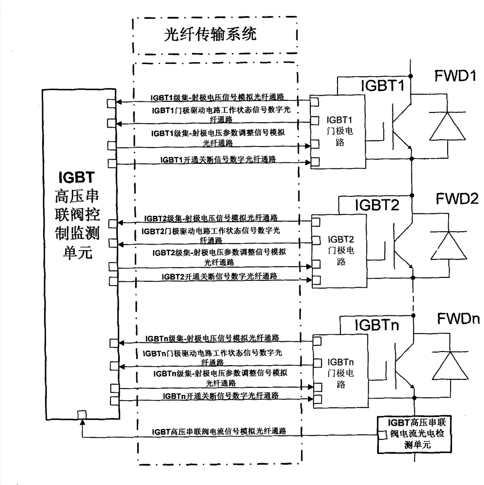
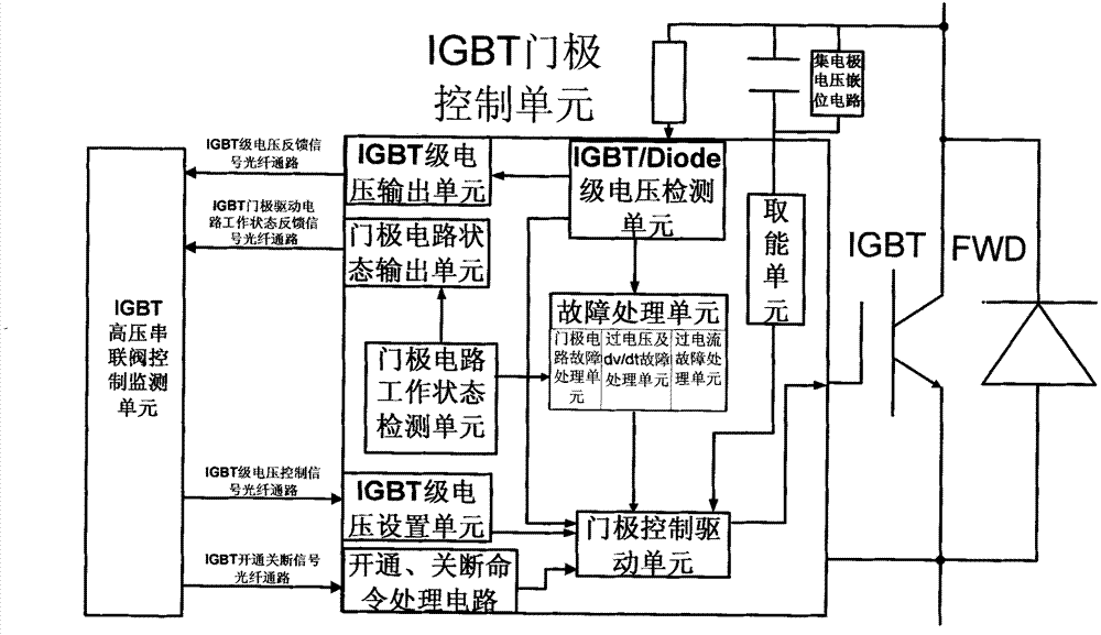
[0031] The block diagram of the IGBT high pressure series valve control and monitoring system is as follows: figure 1 As shown, it mainly includes three parts: IGBT gate circuit, valve control monitoring unit and optical fiber transmission system.

[0032] The optical fiber transmission system consists of two parts: four-channel optical fiber (two high-speed analog signal optical fiber channels, two high-speed digital signal optical fiber channels) for each IGBT level and control monitoring unit; one independent analog signal for each series valve and control detection unit Signal Fiber Channel.

[0033] Four optical fiber channels are used to realize information interaction between the gate circuit of each IGBT and the control and monitoring unit, two of which are high-speed analog signal transmission channels, and two are high-speed digital signal transmission channels. One high-speed analog signal fiber channel is used for real-time monitoring of the voltage state of the I...


PUM


Abstract

A control and monitoring system of IGBT (insulated gate bipolar transistor) high voltage series valves comprises an IGBT gate circuit, a valve control and monitoring unit and an optical fiber transmission system. The valve control and monitoring unit is connected to the IGBT gate circuit by the optical fiber transmission system. The IGBT gate circuit also includes an IGBT periphery circuit mainly composed of capacitor, resistor and collector voltage clamping circuits. The optical fiber transmission system includes four optical fiber channels for connecting the IGBT gate circuit with the valve control and monitoring unit and an independent analog signal optical fiber channel for transmitting a valve current signal to the valve control and monitoring system. The system satisfies various functions of IGBT switching on, IGBT switching off, voltage loss balance control, valve state monitoring and so on.

Description

technical field [0001] The invention belongs to the field of power electronics and power systems, and in particular relates to a new IGBT high-voltage series valve control and monitoring system. Background technique [0002] The semiconductor power switching device that appeared in the mid-1980s - the insulated gate bipolar transistor IGBT (Insulated Gate Biploar Transistor) is a composite device, its input control part is a MOSFET, and the output stage is a bipolar junction transistor. The advantages of MOSFET and power transistor: high input impedance, voltage control, small driving power, fast switching speed, operating frequency up to 10-40kHz, lower saturation voltage, larger voltage and current capacity, and wider safe working area. However, the disadvantage of IGBT is that the voltage and current allowable value of a single IGBT are difficult to increase. In order to apply to high-voltage and high-power fields, the method of connecting IGBTs in series is usually used....

Claims


Application Information

Patent Timeline
Patent Type & Authority Patents(China)
IPC IPC(8): H03K17/567H02M1/32
CPCH03K17/0828H02M1/32H02M1/092H03K17/107
Inventor 温家良于坤山荆平吴锐
Owner CHINA ELECTRIC POWER RES INST
Why Eureka
Try Eureka