Continuous rheomolding device for manufacturing metal plate strips

A rheological deformation, metal strip technology, applied in the direction of metal rolling, etc., can solve the problems of slow continuous casting and rolling efficiency, low cooling intensity, slow casting and rolling speed, etc., to achieve high efficiency, energy-saving production, heat dissipation performance Good, tissue performance-enhancing effect

Inactive Publication Date: 2010-11-24
NORTHEASTERN UNIV
View PDF6 Cites 10 Cited by
  • Summary
  • Abstract
  • Description
  • Claims
  • Application Information

AI Technical Summary

Problems solved by technology

However, there are the following technical problems in the current continuous casting and rolling technology: (1) the casting and rolling speed is slow and the efficiency is low; Rolls are used for cooling, the cooling area is small, and the cooling intensity is low, forcing the rolling speed of the rolls to be very low in the continuous casting and rolling process to ensure sufficient cooling intensity for metal solidification. Therefore, the speed of continuous casting and rolling is slow and inefficient
(2) The microstructure and performance of the product are poor; since the metal sheet obtained by continuous casting and rolling is obtained by cooling and solidifying the liquid metal directly through the roll, although there is some rolling deformation, its structure is basically a casting composed of developed dendrites. state organization, so its organizational performance is poor
(3) The quality of the edge of the product is poor; in the continuous casting and rolling process, due to the lack of control over the shape and size of the edge of the product, defects such as cracks and notches are prone to appear on the edge of the casting and rolling product; Under the action of rolling, the liquid phase components are segregated at the edge, making the structure composition of the cast-rolled strip uneven, affecting the product yield and increasing the production cost
(4) The equipment structure is complex and the control is difficult; in the continuous casting and rolling process, the side sealing, shunting, distribution and temperature control of the molten metal all require special equipment components, and the functions of each component are relatively independent, making the production equipment structure Complex and difficult to control the production process

Method used


Image

  • Continuous rheomolding device for manufacturing metal plate strips
  • Continuous rheomolding device for manufacturing metal plate strips
  • Continuous rheomolding device for manufacturing metal plate strips

Examples


Embodiment 1

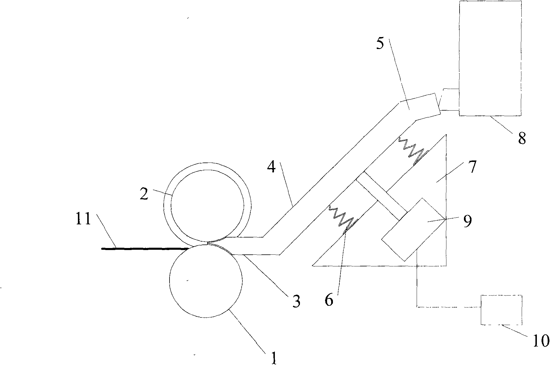
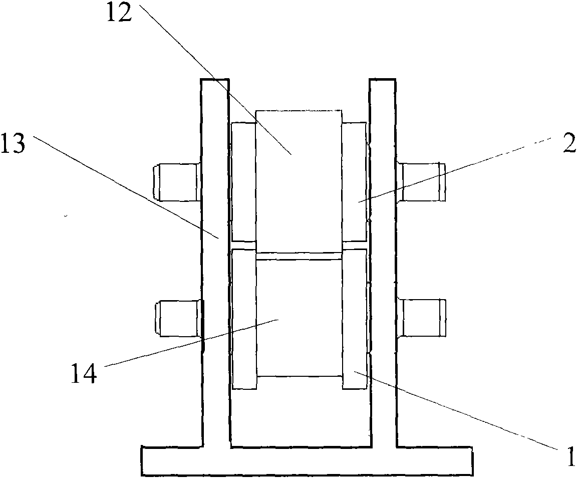
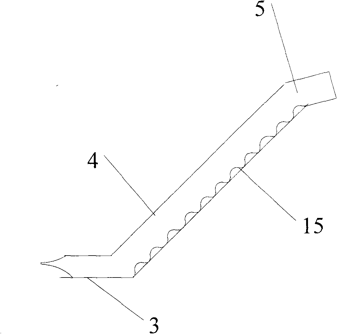
[0028] The structure of the continuous rheological forming device for preparing metal strips is as follows: figure 1 As shown, the device includes an inclined plate, a base 7, an electromagnetic exciter 9 and a two-roll rolling mill. The inclined plate is composed of a feeding section 5, a pulping section 4 and a discharging section 3 connected in sequence, and each section includes a bottom plate and two side plates; the bottom plate of the pulping section is wave-shaped, the bottom of the wave-shaped pulping section bottom plate 15 is connected with the upper end of the spring 6, the lower end of the spring 6 is fixed on the base 7, and one end of the electromagnetic exciter 9 is fixed On the base 7, the other end is connected with the bottom plate of the pulping section 4, and the outlet end of the discharge section 5 is close to the two-roll mill, and the bottom plate and two side plates of the discharge section 5 are connected with the upper roll 1 and the bottom of the tw...

Embodiment 2

[0039] The structure of the continuous rheological forming device for preparing metal strips is the same as in Example 1, the difference is that:

[0040] There is a gap of 1.0 mm between the outlet end of the discharge section and the arc surface of the upper roll, the arc surface of the lower roll, the arc surface of the annular groove and the side of the annular groove.

[0041] The height of the annular boss is smaller than the depth of the annular groove, and the difference between the two is 1.5mm;

[0042] The angle between the bottom surface of the feeding section and the horizontal plane is 50°, and the angle between the pulping section and the feeding section is 140°;

[0043] The top surface of the bottom plate of the pulping section is flat.

[0044] The material of the inclined plate is stainless steel, and the top surface of each section of the inclined plate is closed and provided with a top plate.

[0045] The method of use is the same as in embodiment 1, exc...

Embodiment 3

[0047] The structure of the continuous rheological forming device for preparing metal strips is the same as in Example 1, the difference is that:

[0048] There is a gap of 1.2 mm between the outlet end of the discharge section and the arc surface of the upper roll, the arc surface of the lower roll, the arc surface of the annular groove and the side of the annular groove.

[0049] The height of the annular boss is less than the depth of the annular groove, and the difference between the two is 5mm;

[0050] The angle between the bottom surface of the feeding section and the horizontal plane is 70°, and the angle between the pulping section and the feeding section is 160°;

[0051] The top surface of the bottom plate of the pulping section is wave-shaped, the distance between adjacent wave peaks is 45mm, the distance between adjacent wave peaks and wave troughs is 15mm, and the height difference between adjacent wave peaks and wave troughs is 5mm.

[0052] The method of use i...


PUM


Abstract

The invention provides a continuous rheomolding device for manufacturing metal plate strips. The device comprises an inclined plate, a base, an electromagnetic vibration exciter and a double-roller rolling mill and is characterized by also comprising the double-roller rolling mill, wherein the inclined plate is formed by connecting a feeding section, a pulping section and a discharging section in turn; the lower side of a bottom plate of the pulping section is connected with the upper end of a spring; the lower end of the spring is fixed on the base; one end of the electromagnetic vibration exciter is fixed on the base, and the other end of the electromagnetic vibration exciter is connected with the lower side of the bottom plate of the pulping section; and gaps are formed between the bottom plate and two side plates of the discharging section and the roll surfaces of upper and lower rollers of the double-roller rolling mill. The range of vibration frequency which can be provided by the electromagnetic vibration exciter adopted by the device is expanded greatly and the vibration frequency is adjusted so that an alloy structure can be improved more effectively and molten metal is prevented from crusting on the surface of the inclined plate.

Description

technical field [0001] The invention relates to a forming device for metal strips, in particular to a continuous rheological forming device for preparing metal strips. Background technique [0002] The forming of metal materials is in an important basic position in the development of the national economy, and its development level determines the development level of social production in a certain sense. All kinds of metal sheets and strips play an important role in the forming of metal materials due to their wide application fields, large product consumption and high quality requirements. [0003] Metal semi-solid forming technology is a technology that uses the characteristics of good fluidity of metal with spherical grains in the metal-solid-liquid two-phase region. It has the characteristics of short process, high efficiency and energy saving, and excellent product structure and performance. It has been favored by countries all over the world. It is highly valued and has...

Claims


Application Information

Patent Timeline
Patent Type & Authority Applications(China)
IPC IPC(8): B21B1/46B22D11/06B22D11/10B22D11/055
Inventor 管仁国曹富荣陈礼清赵占勇孙小平
Owner NORTHEASTERN UNIV
Why Eureka
Try Eureka