

Steel pipe concrete flange combining beam with concrete fender
A technology of steel tube concrete and concrete, which is applied in the direction of bridges, bridge parts, bridge construction, etc., can solve the problems of inconvenient construction, complex structure, and undiscovered problems, and achieve the effects of convenient construction, high torsional rigidity, and reduced quantity
- Summary
- Abstract
- Description
- Claims
- Application Information
AI Technical Summary
Problems solved by technology
Method used
Image

Examples
Embodiment 1
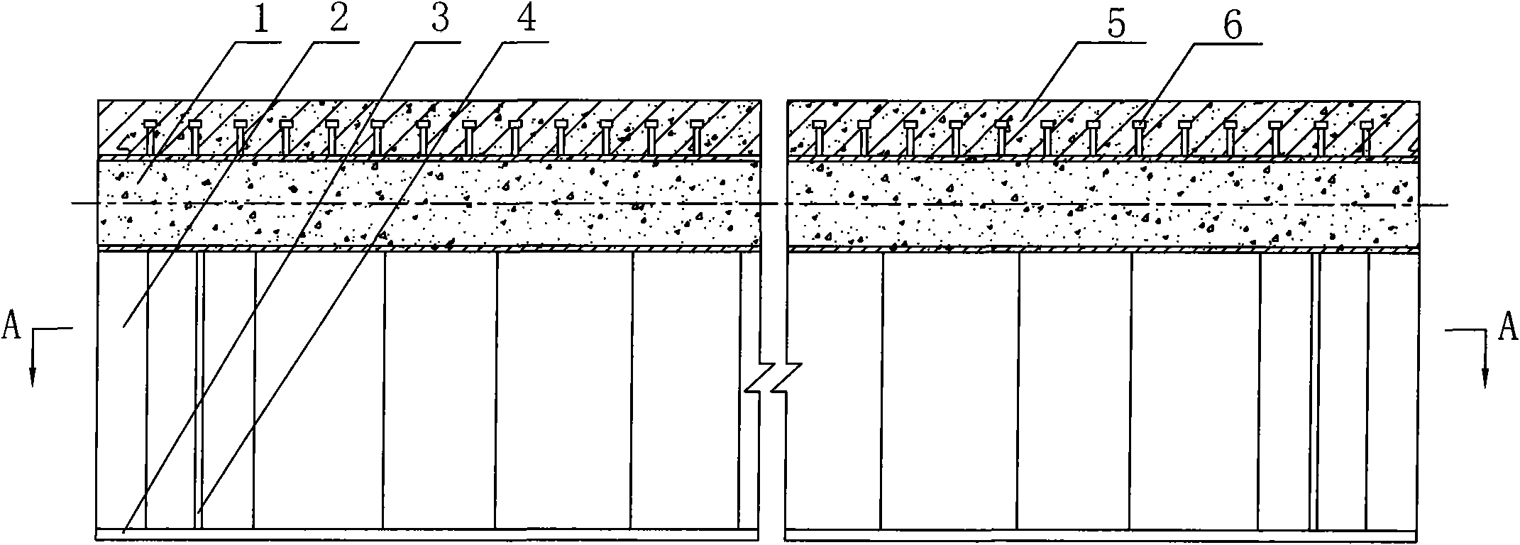
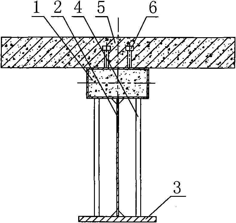
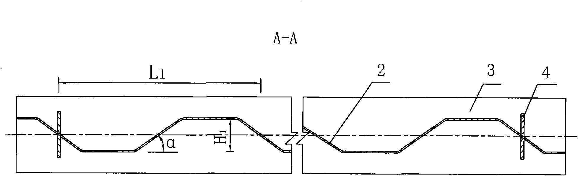
[0033] exist figure 1 , figure 2 , image 3 Among them, the CFST flange composite beam with concrete flanges in this embodiment is composed of rectangular concrete-filled steel pipe upper flanges 1, webs 2, lower flanges 3, stiffeners 4, concrete upper flanges 5, and studs 6. .
[0034] The lower wing plate 3 of the present embodiment is a rectangular steel plate with a length of 4332mm, a width of 200mm, and a thickness of 14mm, and a web 2 with a thickness of 4mm, a height of 306mm, and a length of 4332mm is welded in the longitudinal direction of the lower wing plate 3. 2 is perpendicular to the lower wing plate 3. The shape of the web 2 in this embodiment is a trapezoidal undulating structure, and the horizontal section is a trapezoidal undulating curve in which the head and tail of the isosceles trapezoid and the inverted isosceles trapezoid are connected together. The upper bottom of the isosceles trapezoid The ratio to the lower bottom is 1:2.6, and the angle α betw...
Embodiment 2
[0038] The lower wing plate 3 of the present embodiment is a rectangular steel plate with a length of 1452 mm, a width of 200 mm, and a thickness of 14 mm, and a web 2 with a thickness of 4 mm, a height of 306 mm, and a length of 1452 mm is welded in the longitudinal direction of the lower wing plate 3. 2 is perpendicular to the lower wing plate 3. The shape of the web 2 in this embodiment is a trapezoidal undulating structure, and the horizontal section is a trapezoidal undulating curve in which the head and tail of the isosceles trapezoid and the inverted isosceles trapezoid are connected together. The ratio of the bottom to the lower bottom is 1:2.6, and the angle α between the hypotenuse and the bottom is 37° (wave height H 196mm, wavelength L 1 is 576mm). Stiffeners 4 are welded on the front and rear surfaces of the web 2. The stiffeners 4 are perpendicular to the lower wing 3 and to the web 2. The width of the stiffeners 4 is 58mm and the thickness is 12mm. The spacing ...
Embodiment 3
[0040] The lower wing plate 3 of the present embodiment is a rectangular steel plate with a length of 1200 mm, a width of 100 mm, and a thickness of 10 mm, and a web 2 with a thickness of 3 mm, a height of 200 mm, and a length of 1200 mm is welded in the longitudinal direction of the lower wing plate 3. 2 is perpendicular to the lower wing plate 3. The shape of the web 2 in this embodiment is a trapezoidal undulating structure, and the horizontal section is a trapezoidal undulating curve in which the head and tail of the isosceles trapezoid and the inverted isosceles trapezoid are connected together. The ratio of the bottom to the lower bottom is 1:4, and the angle α between the hypotenuse and the bottom is 30° (wave height H 1 30mm, wavelength L 1 is 173.2mm). The thickness of the stiffener 4 is 4mm. The upper end of the web 2 is welded with a rectangular concrete-filled steel pipe upper flange 1, which is made of self-compacting concrete poured in a rectangular steel pipe ...
PUM
| Property | Measurement | Unit |
|---|---|---|
| Wavelength | aaaaa | aaaaa |
| Width | aaaaa | aaaaa |
| Thickness | aaaaa | aaaaa |
Abstract
Description
Claims
Application Information