Combined drill breaking rocks by cutting method

一种复合式、钻头的技术,应用在钻头、土方钻采、钻井设备等方向,能够解决增加PDC齿工作负荷、钻头失效、加快磨损速度等问题,达到提高破岩效率、磨损均匀、延长使用寿命的效果

Active Publication Date: 2010-11-24
CHENGDU WEIYI PETROLEUM TECH
View PDF3 Cites 67 Cited by
  • Summary
  • Abstract
  • Description
  • Claims
  • Application Information

AI Technical Summary

Problems solved by technology

[0008] Second, the failure of individual teeth on the drill bit (tooth shedding, breakage or excessive wear, etc.) will significantly increase the working load of the PDC teeth near the bottom hole annular zone of the failed tooth, accelerate its wear rate, and lead to premature failure of the drill bit

Method used

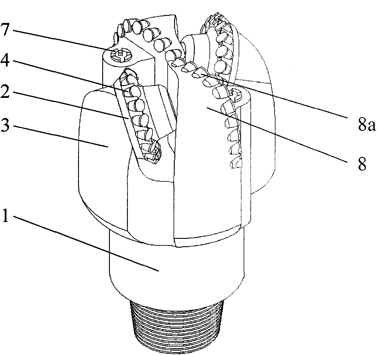
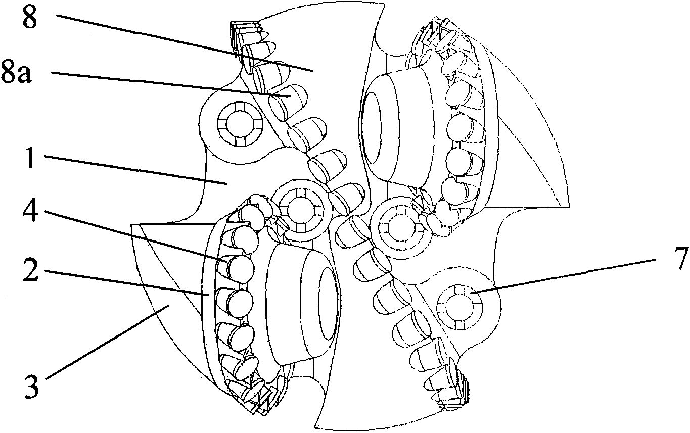
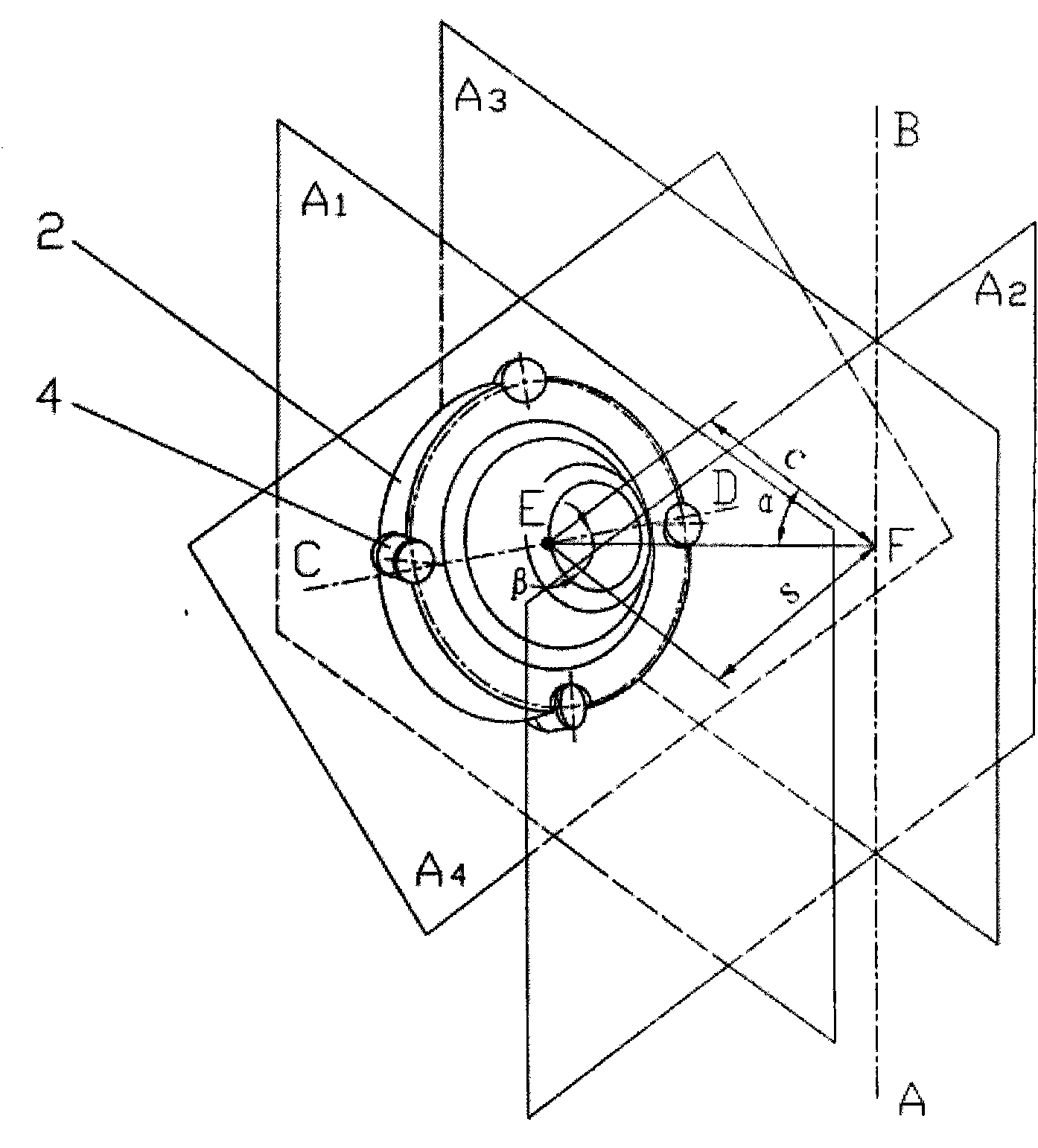

Image

  • Combined drill breaking rocks by cutting method
  • Combined drill breaking rocks by cutting method
  • Combined drill breaking rocks by cutting method

Examples


Embodiment 1

[0066] When the offset angle of the runner 2 is α=±20°, a drill with an outer diameter D=8.5 inches (215.9 mm) is taken as an example (the point farthest from the drill axis on the runner is the drill gauge diameter point). Take the radius r of the outer cutting ring gear 4 of the runner 2 to be 65mm, and the shaft inclination angle β of the runner 2 = 0°, because

[0067] s=c·tan|α| (1)

[0068] ( D 2 ) 2 = ( r + s ) 2 + c 2 - - - ( 2 )

[0069] From equations (1) and (2), it can be obtained that the reference distance c=62.75mm, and the wheel shifting wheel distance s=22.84mm.

[0070] Under the above parameters, the amount of radial slip of the cutting teeth on the outer cutting ring gear 4 of the runner 2 from cutting in to cutting out the bottom hole rock is 41.17mm. According to theoretical calculations and actual experiments that have been done, it can be concluded that the wheel speed ratio at this time is below 0.96...

Embodiment 2

[0074] When the offset angle of the runner 2 is α=±30°, the drill with the outer diameter D=215.9 mm is still taken as an example. Take the radius r of the outer cutting gear ring 4 of the runner as 65 mm.

[0075] According to formulas (1) and (2), the reference distance c=51.62mm, and the wheel distance s=29.81mm of the runner 2.

[0076] Under the above parameters, the radial slip of the cutting teeth is 48.34mm. According to theoretical calculations and actual experiments that have been done, it can be concluded that the wheel speed ratio at this time is below 0.79, and the cutting teeth on the runner 2 can be slowly and alternately moved at the bottom of the well to scrape or cut the rock in turn. . Such as Figure 13 Shown is a schematic diagram of the net-like scratches cut by the drill bit at the bottom of the well under the combined action of the runner cutting unit and the fixed cutting structure when the offset angle of the runner 2 of the present invention is α=30°. ...

Embodiment 3

[0078] When the offset angle of the runner 2 is α=±40°, the values ​​of D and r are the same as above, substituting equations (1) and (2) to obtain, c=41.37mm, s=34.71mm.

[0079] Under the above parameters, the radial slip of the cutting teeth is 53.95mm, and the wheel speed ratio is below 0.64. Such as Figure 14 Shown is a schematic diagram of the net-like scratches cut by the drill bit at the bottom of the well under the combined action of the rotating wheel cutting unit and the fixed cutting structure when the offset angle of the runner 2 of the present invention is α=40°. It can be seen from the figure that the sliding amount of the cutting teeth on the runner at the bottom of the well is longer than when α=±30°.


PUM


Abstract

The invention discloses a combined drill breaking rocks by a cutting method. The combined drill comprises a drill body (1) and a rotating wheel (2), wherein a wheel palm (3) is arranged on the drill body (1); the rotating wheel (2) is arranged on the shaft neck (6) of the wheel palm (3) and is in rotary connection with the wheel palm (3); an external row of cutting gear rings (4) are arranged on the rotating wheel (2); the deviation angle alpha of the rotating wheel (2) is in a range that the absolute value of alpha is more than or equal to 20 degrees and less than or equal to 90 degrees; and a fixed cutting structure (8) with fixed cutting teeth (8a) is arranged on the drill body (1). Cutting teeth on the rotating wheel break the rocks in an alternatively scraping mode and cooperates with the cutting teeth on the fixed cutting structure to form a net-like breaking region on the pit bottom rocks, so the combined drill has the advantages of high rock-breaking efficiency, uniform wear, good cooling effect, long service life of the teeth, long working life of the bearing and long service life of the drill.

Description

Technical field [0001] The invention belongs to the technical field of drilling equipment such as petroleum and natural gas, mining engineering, building foundation engineering construction, geology, hydrology, etc., and specifically relates to a composite drill bit that breaks rock by cutting. Background technique [0002] The drill bit is a rock breaking tool used in drilling engineering to break the rock and form a wellbore. Nowadays, the drill bits used in drilling engineering mainly include cone bits (including tri-cone bits and single-cone bits) and PDC (polycrystalline diamond composite) bits. [0003] The tri-cone drill bit breaks the rock mainly in the form of impact crushing. The wheel speed ratio of the tri-cone bit (the ratio of the rotation speed of the bit to the rotation speed of the bit when the bit is rotating) is greater than 1, and the rotation speed of the bit when the bit is rotating. Quickly, the teeth on the cones form an impact crushing effect on the bottom...

Claims


Application Information

Patent Timeline
Patent Type & Authority Applications(China)
IPC IPC(8): E21B10/43E21B10/46
CPCE21B10/14E21B10/08E21B10/50E21B10/20E21B10/16
Inventor 杨迎新陈炼林敏裴竹任海涛
Owner CHENGDU WEIYI PETROLEUM TECH
Why Eureka
Try Eureka