Hydraulic valve, hydraulic valve bank and control method thereof

A technology of hydraulic valve group and hydraulic valve, applied in the field of hydraulic control system and construction machinery, can solve the problems of difficult to guarantee precision, inconvenient processing and assembly, long matching surface, etc., and achieve easy guarantee of precision, work efficiency and work stability. Improved, even wear effect

Inactive Publication Date: 2010-11-24
SANY HEAVY IND CO LTD (CN)
View PDF1 Cites 17 Cited by
  • Summary
  • Abstract
  • Description
  • Claims
  • Application Information

AI Technical Summary

Problems solved by technology

[0010] The purpose of the present invention is to provide a hydraulic valve, which can solve the problems of long mating surface between the valve core and the valve body, difficulty in ensuring precision, and inconvenient processing and assembly.

Method used


Image

  • Hydraulic valve, hydraulic valve bank and control method thereof
  • Hydraulic valve, hydraulic valve bank and control method thereof
  • Hydraulic valve, hydraulic valve bank and control method thereof

Examples


Embodiment Construction

[0063] It should be noted that, in the case of no conflict, the embodiments in the present application and the features in the embodiments can be combined with each other. The present invention will be described in detail below with reference to the accompanying drawings and examples.

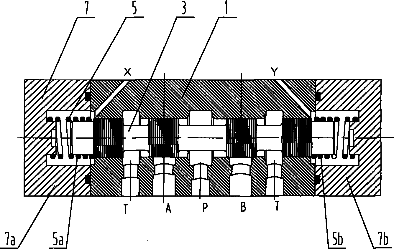
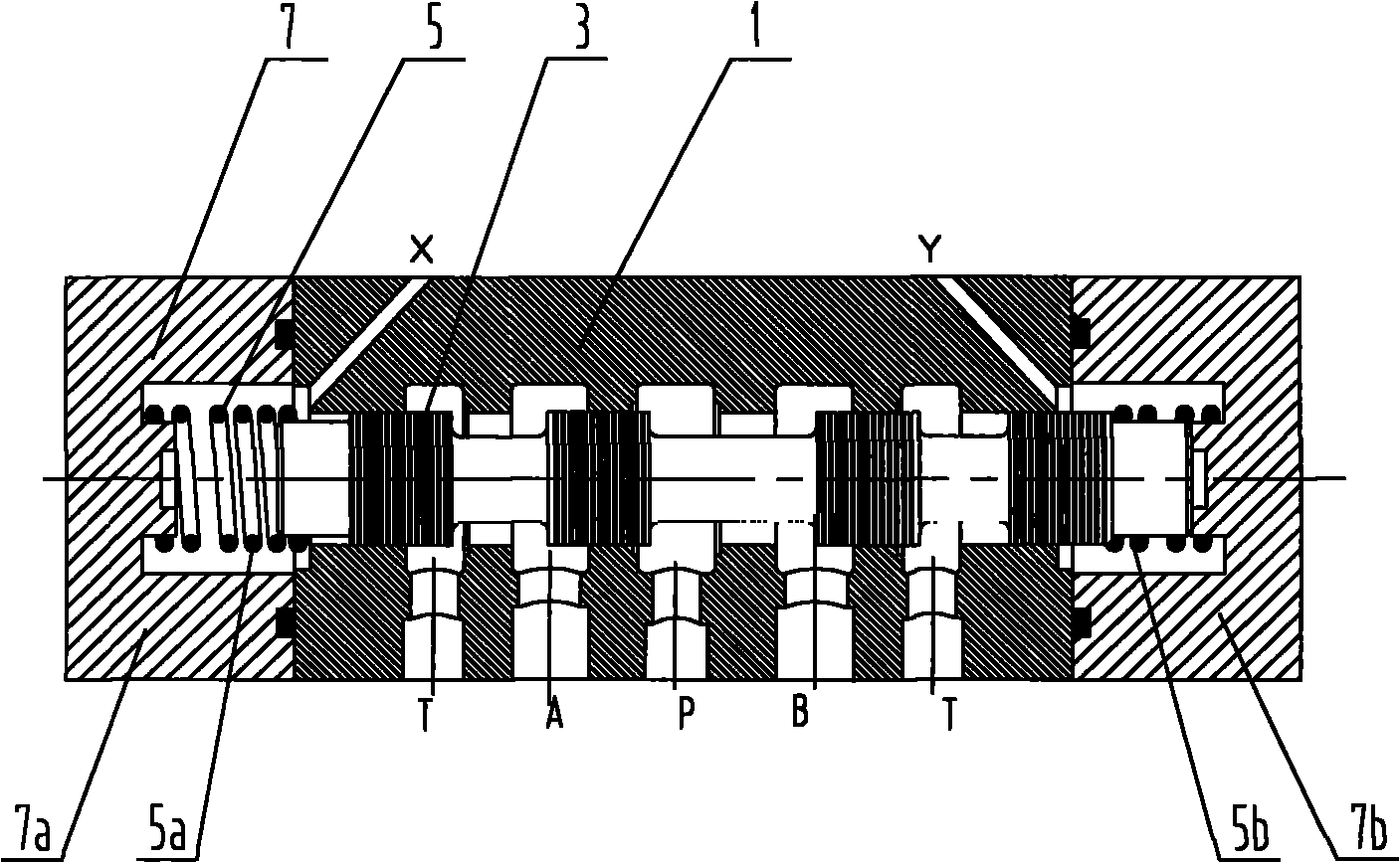
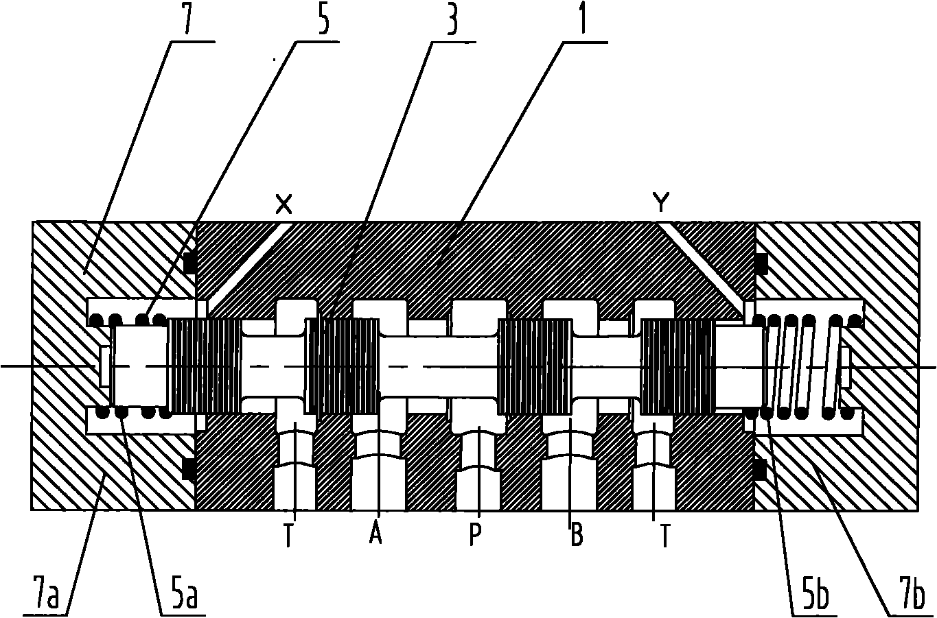
[0064] figure 2 , Figure 2a , Figure 2b They are respectively the structural schematic diagram of the hydraulic valve according to the first embodiment of the present invention, and the schematic diagrams when the hydraulic valve is in the left position and the right position.

[0065] Such as figure 2 As shown, in the first embodiment of the present invention, the hydraulic valve includes a valve body 10 and a spool 30. The spool 30 includes a first spool 31 and a second spool 32. Both spools are arranged on the valve body 10. inside the cavity.

[0066] In the hydraulic valve of the present invention, a stepped surface 311 can be provided on the first end of the first valve core 31, ...


PUM


Abstract

The invention relates to a hydraulic valve, a hydraulic valve bank and a control method thereof. The hydraulic valve comprises a valve body and a valve core, wherein the valve core is arranged in the cavity of the valve body, the valve core is in a split type structure and comprises a first valve core and a second valve core, and a valve pocket can be arranged between the valve body and the valve core. The hydraulic valve bank provided by the invention also comprises a first valve core and a second valve core which form a split type structure, and the valve cores are integrated into a valve block. In the control method of the hydraulic valve and the hydraulic valve bank provided by the invention, oil drain ports R on the valve body or the valve block are simultaneously used as control ports K so as to realize a four-position function. By using the split type valve core structure, the hydraulic valve solves the problems of long matching surface between the valve core and the valve body in the hydraulic valve, difficult accuracy guarantee and inconvenient processing and assembly. Besides, the valve core can not be clamped easily and has high contamination resistance. Additionally, because of the use of the valve pocket, the hydraulic valve has the advantages of good part interchangeability, convenient maintenance and replacement and greatly prolonged overall service life.

Description

technical field [0001] The present invention relates to the technical field of hydraulic transmission and control, in particular to a hydraulic valve and hydraulic valve group for controlling the direction or flow of liquid in a hydraulic system, and the present invention also relates to a hydraulic control system including the hydraulic valve or hydraulic valve group, construction machinery. Background technique [0002] Hydraulic valves used for fluid direction control or flow control in hydraulic systems are widely used and there are many types. According to the operation mode, there are electric, hydraulic, electro-hydraulic, etc. According to the structure of the valve, there are various forms such as slide valve and rotary valve. [0003] figure 1 Shown is an existing spool type hydraulic valve structure. Such as figure 1 As shown, the hydraulic valve includes a valve body 1 , a valve core 3 , a spring 5 and an end cover 7 . The valve core 3 is set in the cavity o...

Claims


Application Information

Patent Timeline
IPC IPC(8): F15B13/02
CPCF16K11/07F16K27/041F15B13/0402
Inventor 易小刚刘永东
Owner SANY HEAVY IND CO LTD (CN)
Why Eureka
Try Eureka