Celestial autonomous navigation method based on star sensors

A star sensor and autonomous navigation technology, applied in the field of astronomical navigation, can solve the problems of difficult to establish atmospheric mathematical model, reduce the output attitude of the star sensor, etc., to avoid measurement and control errors and improve measurement accuracy.

Inactive Publication Date: 2010-11-24
HARBIN INST OF TECH
View PDF3 Cites 43 Cited by
  • Summary
  • Abstract
  • Description
  • Claims
  • Application Information

AI Technical Summary

Problems solved by technology

However, due to the influence of the atmosphere, seasonal changes, climate and other factors, it is difficult to establish a more accurate mathematical model of the atmosphere internationally.
Moreover, with this navigation method, part of the starlight in the field of view must pass through the atmosphere, causing deviations in the positions of these stars on the image plane of the star sensor, thereby reducing the output attitude of the star sensor

Method used


Image

  • Celestial autonomous navigation method based on star sensors
  • Celestial autonomous navigation method based on star sensors
  • Celestial autonomous navigation method based on star sensors

Examples


Embodiment 1

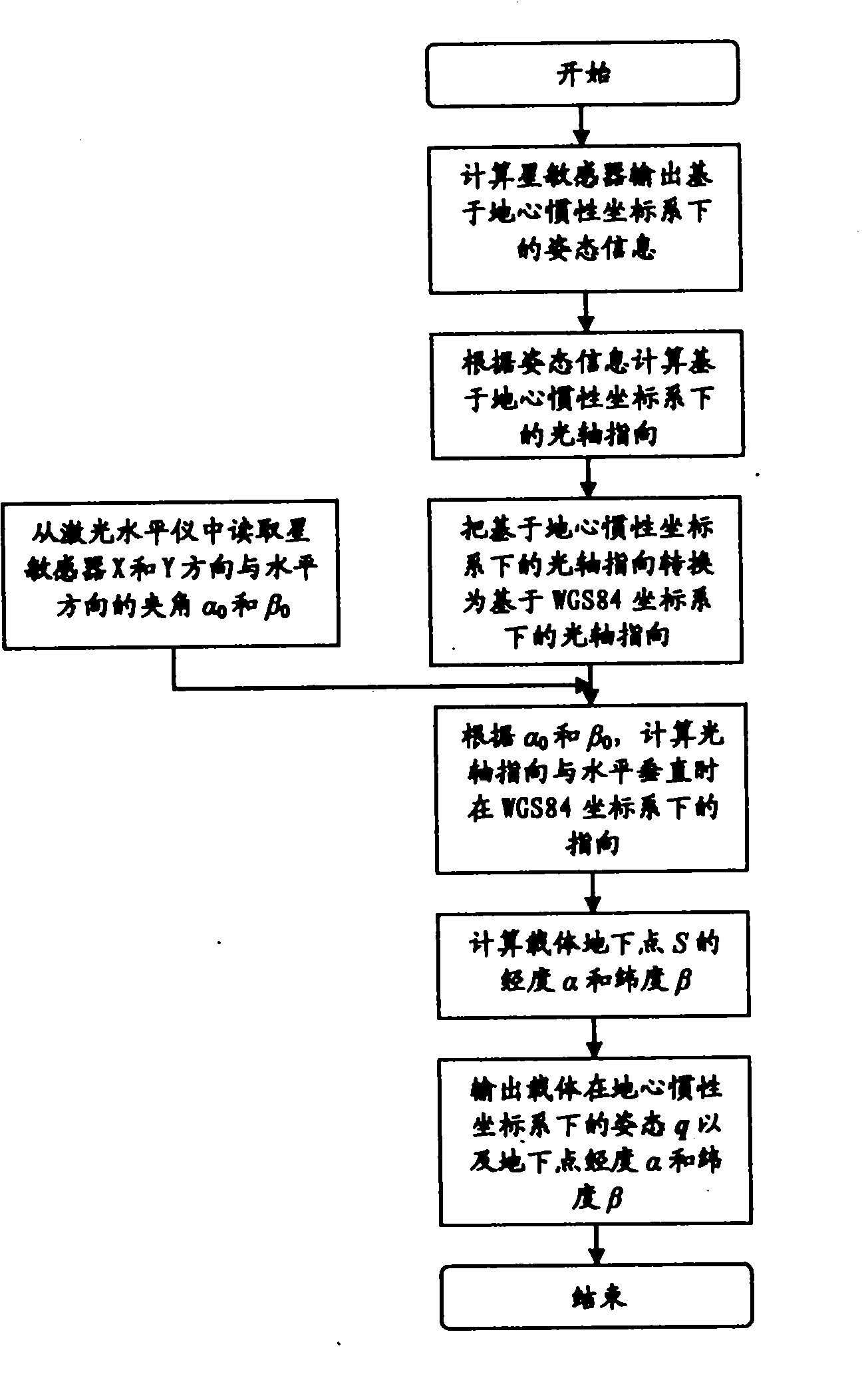
[0029] Example 1: Combining figure 1 , figure 2 A kind of celestial self-navigation method based on star sensor of the present invention, the steps are as follows:

[0030] Step 1: Calculate the attitude information that the star sensor outputs based on the earth-centered inertial coordinate system;

[0031] Step 2: Calculate the direction of the optical axis based on the geocentric inertial coordinate system according to the attitude information;

[0032] Step 3: Convert the optical axis pointing based on the geocentric inertial coordinate system to the optical axis pointing based on the WGS84 coordinate system; read the angle α between the X and Y directions of the star sensor and the horizontal direction from the laser level 0 and beta 0 ;

[0033] Step 4: According to α 0 and beta 0 Calculate the direction of the optical axis in the WGS84 coordinate system when the direction of the optical axis is perpendicular to the horizontal;

[0034] Step 5: Calculate the long...

Embodiment 2

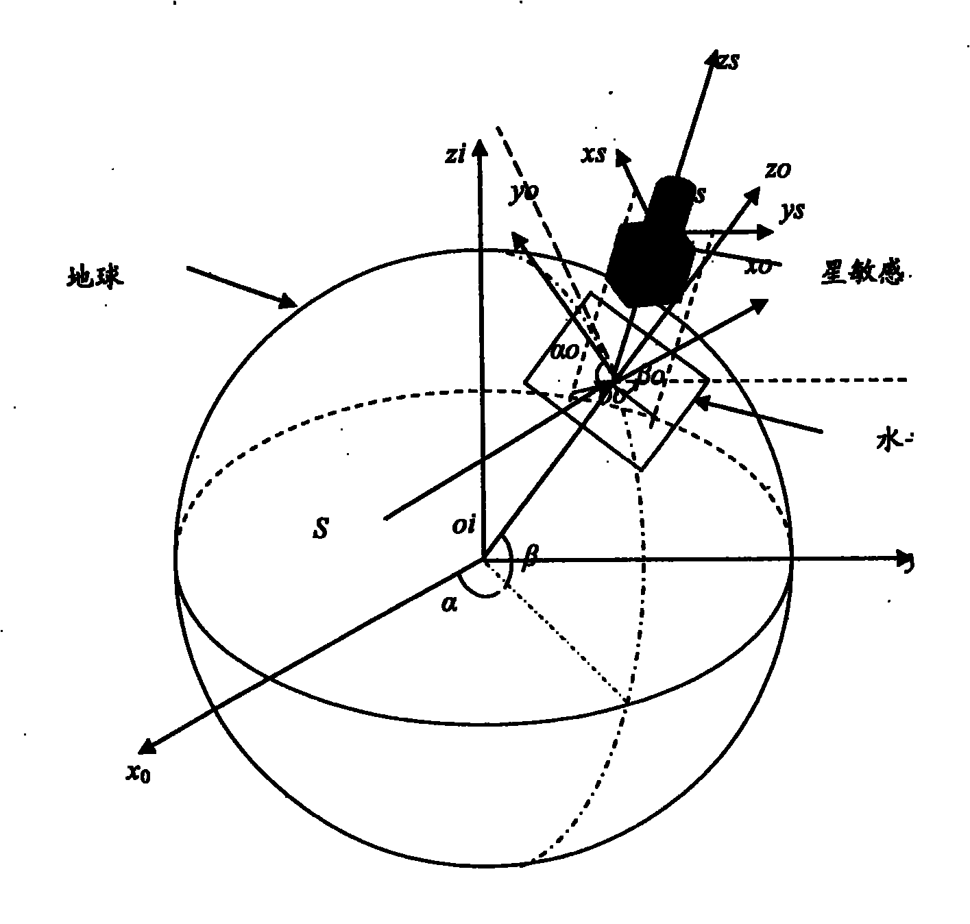
[0036] Example 2: Combining Figure 1-Figure 4In order to truly realize autonomous navigation, the celestial navigation system mainly needs to solve the following problems: get rid of the constraint of horizontal reference provided by inertial equipment and obtain the physical quantity of carrier navigation information. It can be seen that to get rid of the restriction of the horizontal reference and to seek the measurement physical quantity of the carrier navigation information is the necessity of realizing high-precision astronomical navigation. The purpose of the invention is to set up an astronomical autonomous navigation system based on a star sensor. The whole system as figure 1 shown. Each coordinate system is defined as follows:

[0037] Geocentric inertial coordinate system O 0 -x 0 the y 0 z 0 : Coordinate origin O 0 At the Earth's center of mass, x 0 Axis points to T 0 The equinox of the moment, z 0 Axis points to T 0 the flat pole of the moment, y 0 ax...

Embodiment 3

[0087] Example 3: Binding Figure 5 , Figure 6 , the present invention is an astronomical autonomous navigation method based on a star sensor, which includes three subsystems: a star sensor system and two laser level measurement systems. The three-axis attitude of the main carrier of the star sensor; the two laser level measurement systems mainly measure the angle between the two axes of the carrier and the horizontal plane.

[0088] Working process: The star is imaged on the image plane of the star sensor (such as CCD or APS) through the optical lens of the star sensor, and the imaging circuit converts the electrical signal of the star in the image plane into a complete star map and stores it in the memory ; The star image extraction software reads the star map data in the memory, and extracts the star image coordinates from the star map; (if the star sensor has prior information, the star map recognition software uses the star tracking algorithm); the attitude calculation...


PUM


Abstract

The invention provides a celestial autonomous navigation method based on star sensors, which comprises the following steps: calculating attitude information based on a geocentric inertial coordinate system, which is output by a star sensor; calculating the optical axis direction based on the geocentric inertial coordinate system; converting the optical axis direction based on the geocentric inertial coordinate system into optical axis direction based on a WGS84 coordinate system; reading the included angles alpha 0 and beta 0 between the X and Y directions of the star sensor and the horizontal direction from a laser level meter; calculating the direction in the WGS84 coordinate system when the optical axis direction is perpendicular to the horizontal level; calculating the longitude alpha and latitude beta of the underground point S of the carrier; and outputting the attitude q and the longitude alpha and latitude beta of the underground point of the carrier in the geocentric inertial coordinate system. The invention avoids measurement and control errors caused by horizontal reference platforms, enhances the measuring accuracy, and simultaneously outputs the attitude of three axes and the longitude and latitude of the carrier in the geographic coordinate system in real time, thereby completely realizing celestial autonomous navigation.

Description

(1) Technical field [0001] The invention relates to celestial navigation technology, in particular to a celestial autonomous navigation method based on a star sensor. (2) Background technology [0002] In the late 1960s and early 1970s, inertial technology began to be applied to various surveying and mapping tasks. The United States developed the inertial positioning and orientation system, referred to as the PADS system. After the carrier vehicle equipped with the inertial positioning and orientation system travels a tortuous distance on the ground, the horizontal position accuracy determined by the system is 20 meters, and the root mean square error of the height is 10 meters. This technological achievement is obviously of great significance to the application of inertial technology. [0003] After the successful development of the inertial positioning and orientation system, the U.S. Army successively developed the inertial positioning system (Inertial Position System, ...

Claims


Application Information

Patent Timeline
Patent Type & Authority Applications(China)
IPC IPC(8): G01C21/02
Inventor 李葆华李清华王常虹刘睿
Owner HARBIN INST OF TECH
Why Eureka
Try Eureka