
Method for the keyhole-free laser fusion cutting using leading and trailing laser beams

A laser beam and cutting direction technology, applied in laser welding equipment, welding equipment, metal processing equipment, etc., can solve the problems of poor cutting edge basic pattern image, time instability, poor cutting edge roughness, etc., to achieve small The effect of affecting the image of the scar

Active Publication Date: 2010-11-24
TRUMPF WERKZEUGMASCHINEN GMBH & CO KG
View PDF5 Cites 6 Cited by
  • Summary
  • Abstract
  • Description
  • Claims
  • Application Information

AI Technical Summary

Problems solved by technology

This is temporally unstable and results in the poorer cut edge basic ruffle profile and poorer cut edge roughness known in solid state laser fusion cutting
Previous laser beam fusion cutting in stainless steel with the aid of a solid-state laser showed poor cut edge quality, increased burr generation and increased oxidation on the cut flanks from sheet thicknesses greater than 2 mm

Method used


Image

  • Method for the keyhole-free laser fusion cutting using leading and trailing laser beams
  • Method for the keyhole-free laser fusion cutting using leading and trailing laser beams
  • Method for the keyhole-free laser fusion cutting using leading and trailing laser beams

Examples


Embodiment Construction

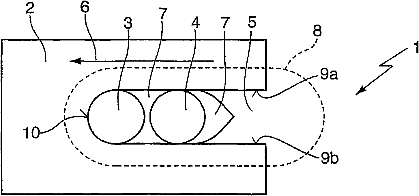
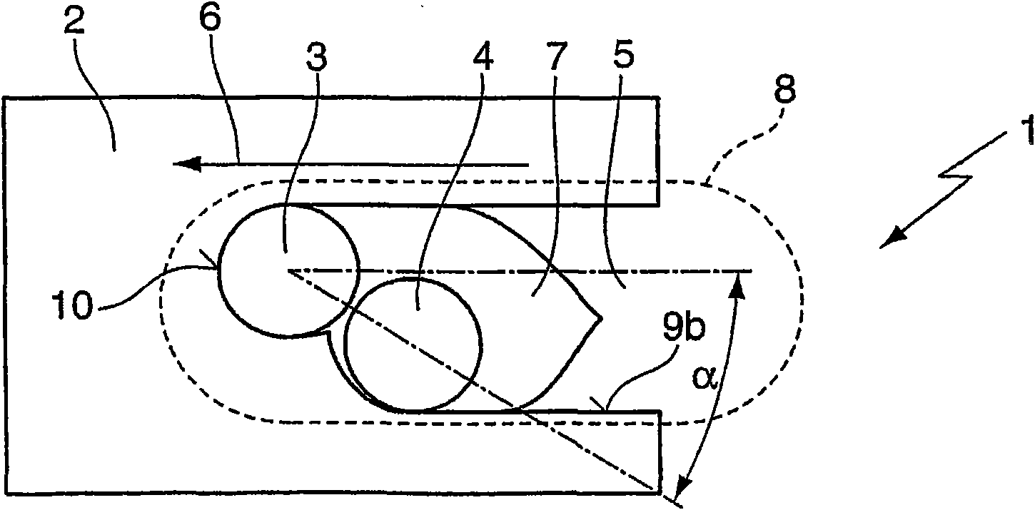
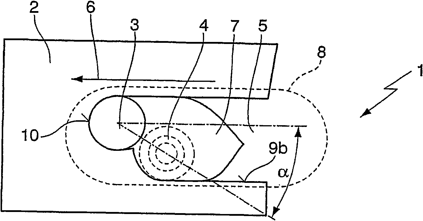
[0017] exist figure 1 The beam assembly 1 shown in is used for laser fusion cutting of a workpiece 2 by means of a leading laser beam 3 and a concentrically following laser beam 4 , which are irradiated on the workpiece 2 from above. The preceding laser beam 3 is moved in the cutting direction 6 along the kerf 5 to be produced and carries out the actual cutting, wherein the melt 7 produced here is extracted from the already high-pressure inert gas jet discharged from the nozzle 8 . The resulting kerf 5 exits downwards. The following laser beam 4 in the cutting direction 6 has the same beam diameter and the same energy on the workpiece 2 as the preceding laser beam 3 . The advantage of this beam assembly is the faster cutting speed compared to conventional laser fusion cutting without the following laser beam 4 .

[0018] In all shown embodiments, the focal point of this trailing laser beam 4 is arranged in the trailing part of the cutting front 10, and with a bifocal optic (...


PUM

PropertyMeasurementUnit
wavelengthaaaaaaaaaa

Abstract

In a method for the keyhole-free fusion cutting of a workpiece (2), wherein the workpiece (2) is fused by a laser beam (3) along a kerf (5) to be produced and the resulting melt (7) is driven out of the produced kerf (5) by a gas jet with high pressure, according to the invention at least one laser beam (4) trails the laser beam (3) in the cutting direction (6) and influences the melt (7) such that at least one of the two cutting flanks (9a, 9b) of the workpiece (2) has a better cutting quality than without the trailing laser beam (4).

Description

technical field [0001] The invention relates to a method for fusion-cutting a workpiece without keyholes, wherein the workpiece is melted by means of a laser beam along the kerf to be produced and the resulting melt is passed through a high-pressure The gas jet exits the resulting kerf. Background technique [0002] In the known conventional laser fusion cutting, with the help of CO 2 A laser beam from a laser or solid-state laser melts the material and an inert gas (such as nitrogen or argon) blows the melt and slag down the kerf at high pressure. The formation of the melt pool and the resulting melt flow vector are related to absorption. In contrast to conventional laser fusion cutting, in so-called pinhole laser cutting, the material is not only melted, but also vapor is generated. If the steam flows out, the steam exerts pressure on the melt and displaces the solution, thereby creating elongated steam capillaries (pores). The vapor capillary is surrounded by melt and...

Claims


Application Information

Patent Timeline
Patent Type & Authority Applications(China)
IPC IPC(8): B23K26/06B23K26/067
CPCB23K26/38B23K26/1405B23K26/0608B23K26/0613B23K26/142
Inventor T·霍夫曼
Owner TRUMPF WERKZEUGMASCHINEN GMBH & CO KG
Learn More