
Optical rain sensor device for a motor vehicle

A sensing device and rainwater technology, applied in vehicle cleaning, vehicle maintenance, transportation and packaging, etc., can solve the problems of optical performance and impact of polluted optical components

Inactive Publication Date: 2010-11-24
ROBERT BOSCH GMBH
View PDF1 Cites 6 Cited by
  • Summary
  • Abstract
  • Description
  • Claims
  • Application Information

AI Technical Summary

Problems solved by technology

[0006] Contamination can also adversely affect the optical performance of optical components

Method used


Image

  • Optical rain sensor device for a motor vehicle
  • Optical rain sensor device for a motor vehicle

Examples


Embodiment Construction

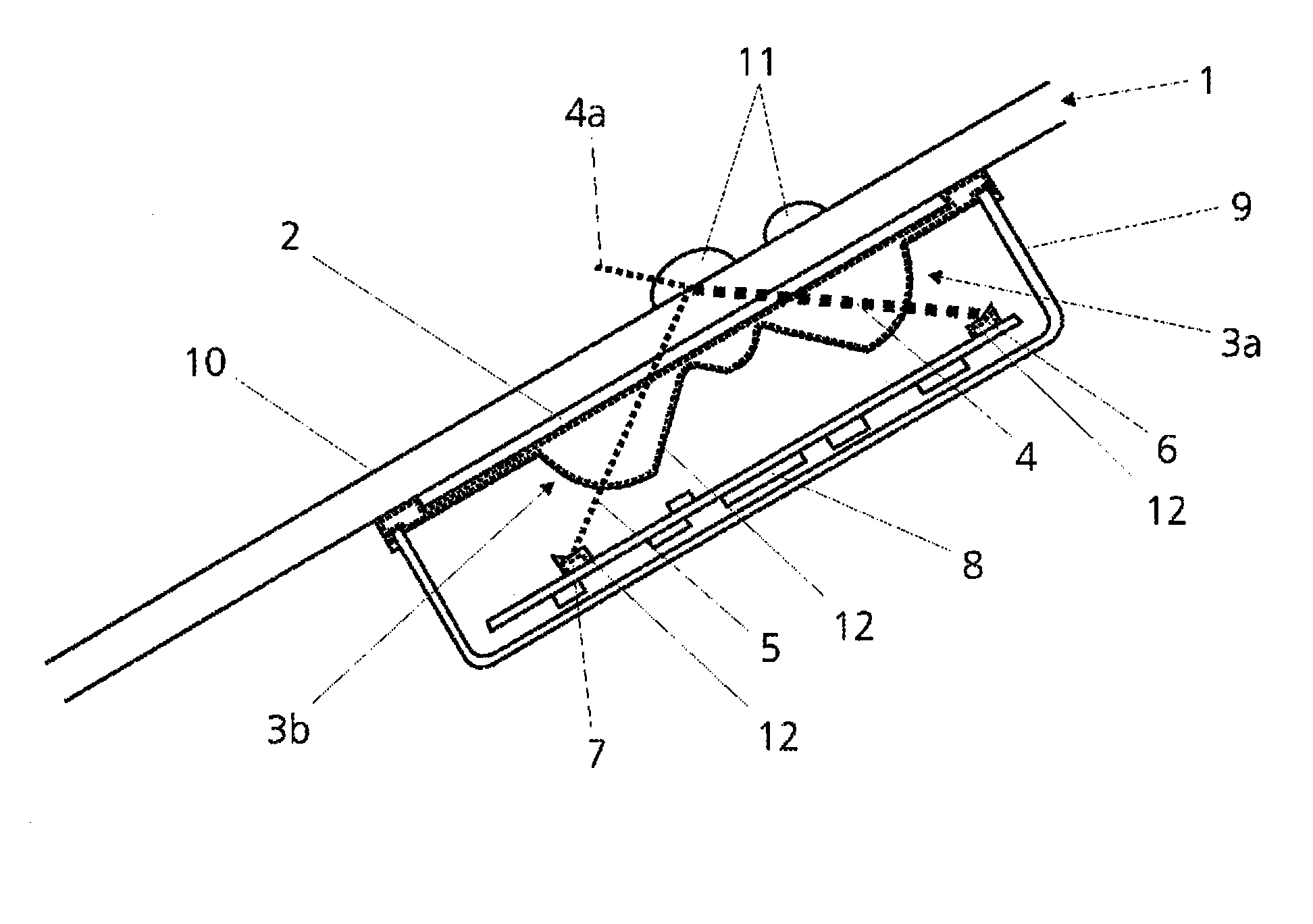
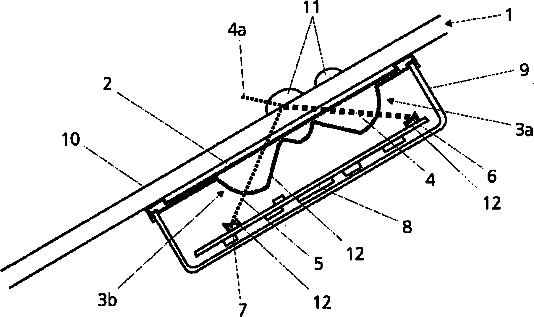
[0013] An optical rain sensor according to the invention is depicted in the drawing, which works according to the principle described below.

[0014] A source of electromagnetic radiation 6 (for example an infrared LED or similar) is emitted at a defined angle from the inside of the glass or windshield 1 (i.e. generally from the passenger compartment of a motor vehicle not shown) in the direction of the windshield 1 Electromagnetic radiation 4 (so-called useful light) emerges. This beam 4 passes through the interface between the interior and the windshield 1 and is deflected at the interface 10 formed by the windshield 1 and the outside of the vehicle, which in this region is referred to as the sensitive surface. The light beams are generally parallel in the windshield 1 . The angle of incidence of the electromagnetic beam 4 relative to the interface 10 is selected in such a way that the electromagnetic beam 4 strikes the windshield at the interface 10 according to optical la...


PUM


Abstract

The invention relates to an optical rain sensor device for a motor vehicle, having several structural elements (3a,3b,6,7), specifically at least one electromagnetic radiation source (6), at least one receiving device (7), at least one transmitting optical system (3a) and at least one receiving optical system (3b), wherein electromagnetic radiation (4,5) emitted by at least one radiation source (6) can be received by means of at least one receiving device (7), wherein the electromagnetic radiation (4,5) is forwarded by at least one radiation source (6) by means of at least one transmitting optical system (3a) to a limiting surface (10) of the windshield (1) of the motor vehicle with the motor vehicle exterior, is reflected there and is sent on by means of at least one receiving optical system (3b) to at least one receiving device (7). The surface of at least one of the structural elements (3a,3b,6,7) is provided at least partially with a nanocoating (12) which effects a photocatalytic self-cleaning of the surface.

Description

technical field [0001] The invention relates to an optical rain sensor device for motor vehicles according to the preamble of claim 1 . Background technique [0002] Optical rain sensors or rain sensor arrangements for motor vehicles are known from the prior art, which are connected to the windshield within the vehicle cabin via a coupling medium (for example silicone). In this case, the optical rain sensor directs the beam of the transmitter or radiation source into the windshield via a lens system (ie transmitter optics). This light is totally reflected at the glass surface and is directed through another lens or receiver optics into a light detector or receiver. The more water on the glass surface of the windshield, the weaker the reflection and therefore the weaker the signal measured by the light detector. The optical rain sensor can control the car's wiper device according to the amount of rain detected, and automatically select the most effective level of wiper spee...

Claims


Application Information

Patent Timeline
IPC IPC(8): B60S1/08
CPCB60S1/0848B60S1/0837
Inventor R·博查特
Owner ROBERT BOSCH GMBH
Learn More