Eureka AIR delivers breakthrough ideas for toughest innovation challenges, trusted by R&D personnel around the world.

Method for providing improved driveability for a vehicle

A driver and vehicle traction technology, applied in vehicle components, hybrid vehicles, driver input parameters, etc., to solve problems such as LOS drive mode unavailability

Inactive Publication Date: 2010-12-01
FORD GLOBAL TECH LLC
View PDF6 Cites 5 Cited by
  • Summary
  • Abstract
  • Description
  • Claims
  • Application Information

AI Technical Summary

Problems solved by technology

[0004] In the case of HEVs of the type described in, for example, US Patent No. 6,994,360, the conventional LOS drive mode is not available because of the powertrain architecture of that type of HEV

Method used


Image

  • Method for providing improved driveability for a vehicle
  • Method for providing improved driveability for a vehicle
  • Method for providing improved driveability for a vehicle

Examples


Embodiment Construction

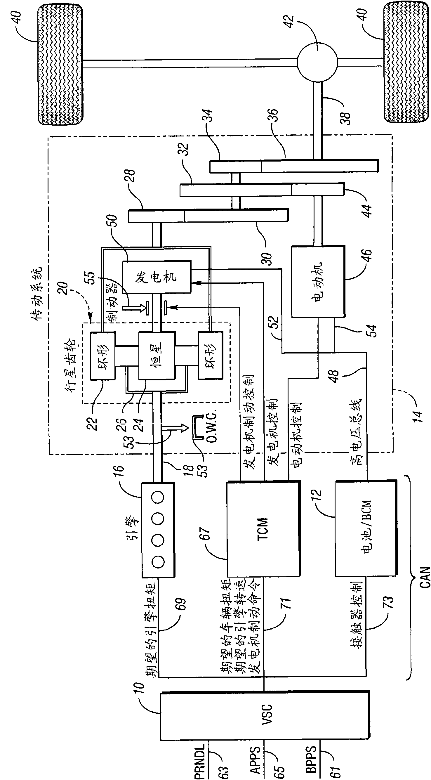
[0023] For the purpose of describing the operating environment of a HEV powertrain including a controller, the Figure 1a A description is made wherein the controller is programmed to use the strategies of the present invention. Figure 1a The power-split hybrid electric vehicle power system shown includes: an engine serving as a first power source; a second power source including at least one electric motor and a high-voltage battery. These power sources establish mechanical and electromotive power flow paths. The mechanical power flow path transfers engine power to the vehicle's traction wheels by controlling the generator speed, whereby the powertrain can behave in a manner similar to a continuously variable transmission in which vehicle speed does not change in response to changes in engine speed. Will Figure 1a The combination of electric motors, generators, and planetary gear trains shown defines an electromechanical, continuously variable power flow path.

[0024] Fig...


PUM


Abstract

A method for controlling torque delivery in a vehicle powertrain using an enhanced limited operating strategy. The strategy is implemented when a powertrain controller fails to respond properly to a driver command for traction wheel torque whereby a modified wheel torque at vehicle traction wheels under driver control is made available.

Description

technical field [0001] The present invention relates to a vehicle power system, in which provision is made for the transmission of power to the traction wheels of the vehicle in the event of failure of a power system control signal. Background technique [0002] In the automotive industry, it is common practice to establish a limited power-run strategy for a vehicle's powertrain in the event of a powertrain control failure. This involves using vehicle crawl mode during so-called "quit on the road" (QOR) events. Operation of the powertrain creep mode will allow the driver of the vehicle to move the vehicle off the road upon failure of the driver-initiated acceleration control signal for the powertrain. In the automotive industry this operating strategy is known as a limited operating strategy (LOS). This is initiated by the deactivation of a signal, which can be identified by the same abbreviation. [0003] The LOS drive mode is used in other faults involving accelerator p...

Claims


Application Information

Patent Timeline
Patent Type & Authority Applications(China)
IPC IPC(8): B60W10/06B60W10/08B60W10/10B60W10/18B60W20/00B60W30/18
CPCY02T10/6239Y02T10/6286B60L2240/423B60W2520/10B60W2540/12B60W10/06B60K6/365B60L2240/486B60W2710/083B60W2540/16B60K6/445B60W20/00B60W2520/105B60W2710/0666B60K1/02B60W50/0098Y02T10/56Y02T10/642B60W50/16B60W10/08Y02T10/62Y02T10/64B60W2050/0012B60W2050/0031B60W30/18063Y02T10/40
Inventor 格雷格·爱德华·高施尔约翰·普罗耶蒂
Owner FORD GLOBAL TECH LLC
Why Eureka
Eureka Blog
Learn More