Warp loom yarn tension compensating device

A compensation device and yarn tension technology, applied in warp knitting, textiles, papermaking, knitting, etc., can solve problems such as inability to meet yarn tension compensation requirements, missing stitches, and knitting speed limitations

Inactive Publication Date: 2010-12-01
CHANGZHOU RUNYUAN WARP KNITTING MACHINERY
View PDF6 Cites 3 Cited by
  • Summary
  • Abstract
  • Description
  • Claims
  • Application Information

AI Technical Summary

Problems solved by technology

The existing warp knitting machine compensates the yarn tension through the above-mentioned device, and thus ensures the smooth progress of the knitting movement, but this yarn tension compensating device has the following disadvantages when the yarn is knit into a loop, that is, due to the knitting The main shaft only swings back and forth, and the tension compensated by the yarn tension compensation device controlled by it corresponds to the frontmost position and the last position during the swinging process of the knitting main shaft respectively, and the frontmost position and the last position when the knitting main shaft swings are respectively Corresponding to the front position and the last position that the knitting needle swings to reach during the knitting motion, when the knitting needle is at the front position or the last position, the yarn is subjected to the minimum or maximum tension, and the tension that the yarn needs to compensate during the knitting motion is not only in the knitting The front

Method used


Image

  • Warp loom yarn tension compensating device
  • Warp loom yarn tension compensating device
  • Warp loom yarn tension compensating device

Examples


Embodiment Construction

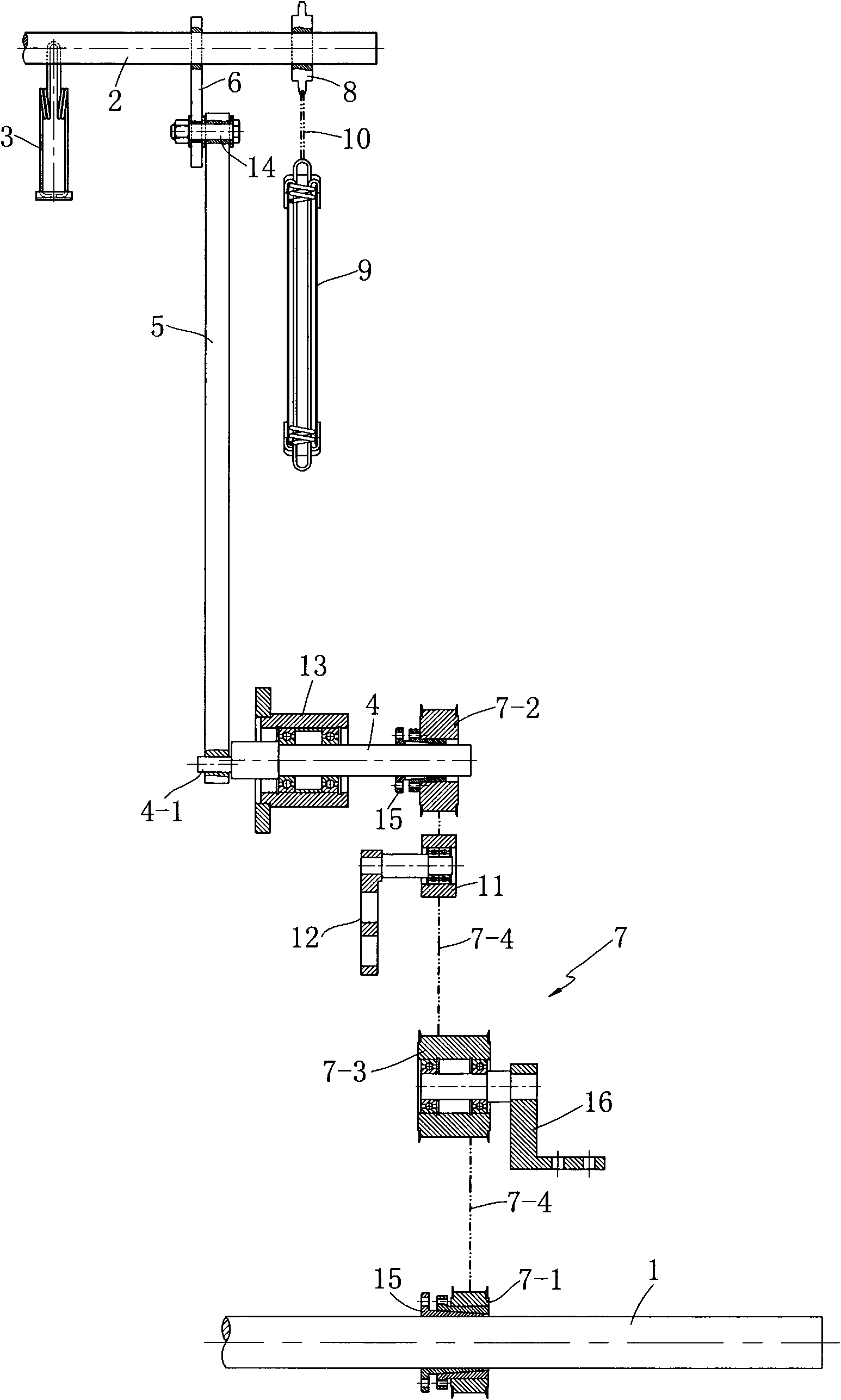
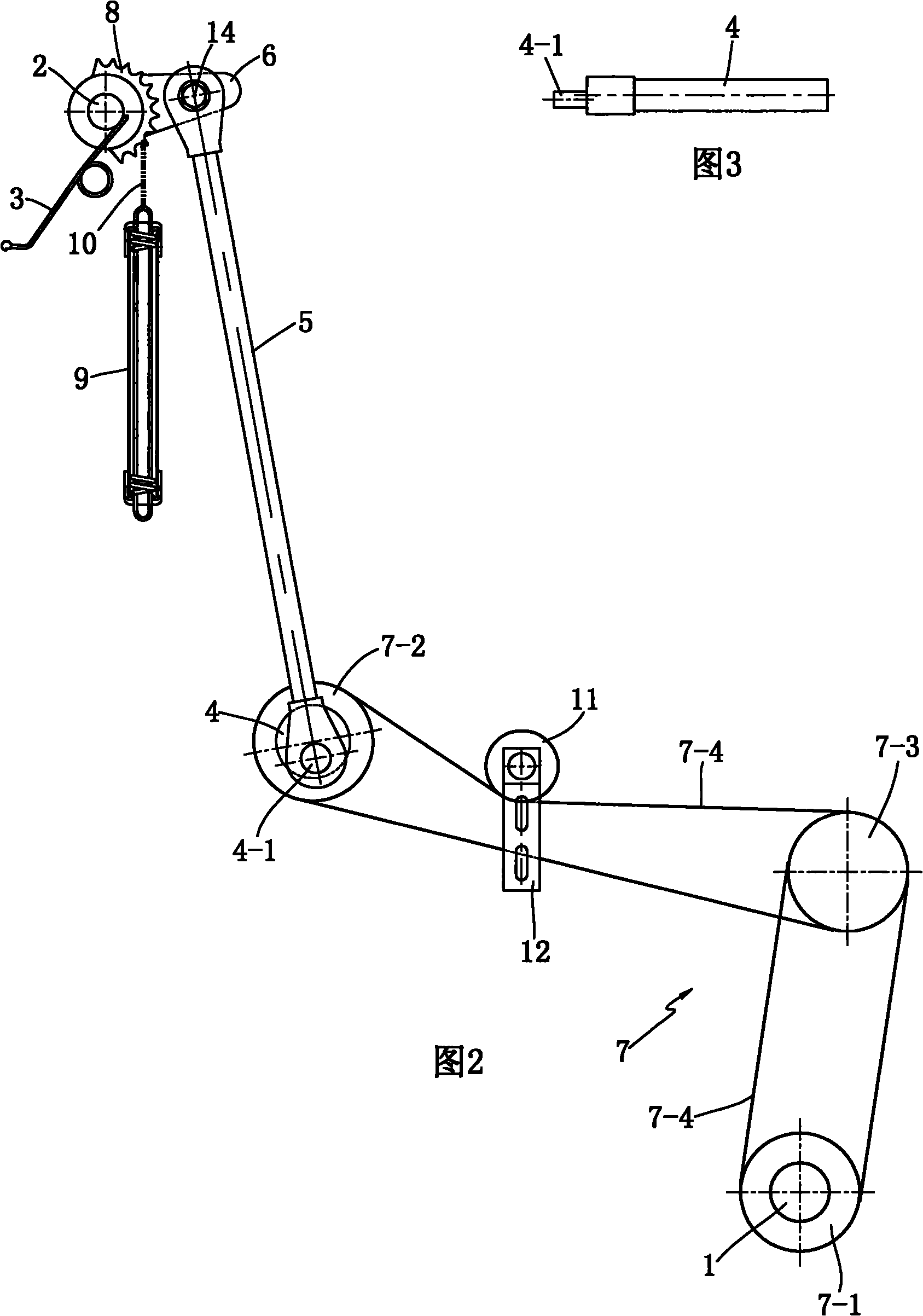
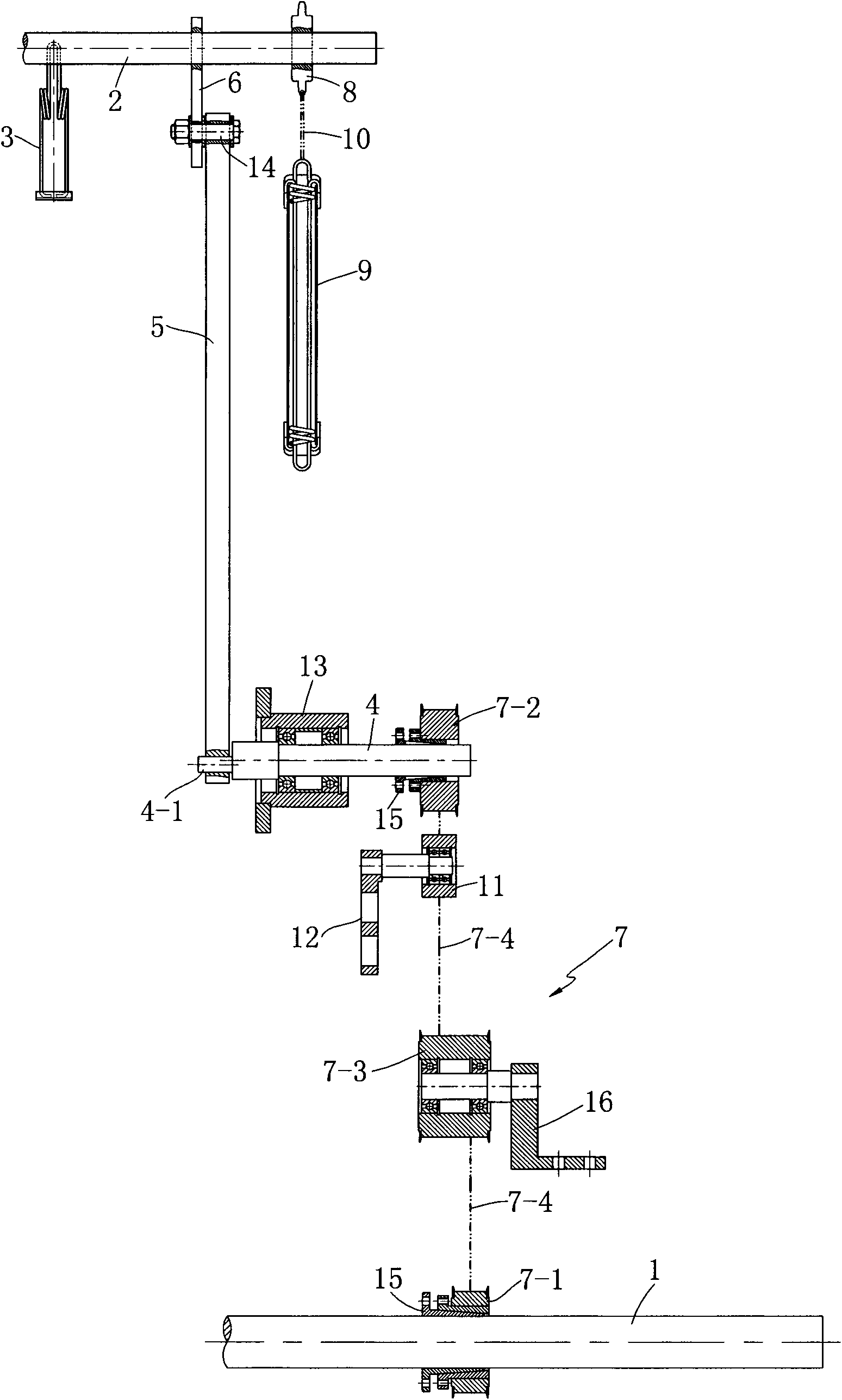
[0013] see figure 1 , 2 , a kind of warp knitting machine yarn tension compensating device shown in 3, comprises the transmission main shaft 1 that is installed in the oil tank of warp knitting machine rotatably, the tension rod 2 that is installed in the warp knitting machine frame rotatably and is fixedly installed in the The tension sheet 3 on the tension rod 2, the tension compensation device also includes an eccentric shaft 4, a connecting rod 5, a swing sleeve 6, and an eccentric shaft 4 that is rotatably installed on the warp knitting machine frame and is arranged on the transmission main shaft 1 and the eccentric shaft 4. The transmission mechanism 7 between them; one end of the swing sleeve 6 can be fixedly connected with the tension rod 2 through a bolt, and the other end is rotatably connected with the upper end of the connecting rod 5 through a short shaft 14; the lower end of the connecting rod 5 It is rotationally connected with one end 4 - 1 of the eccentric sh...


PUM


Abstract

The invention discloses a warp loom yarn tension compensating device which comprises a transmission main shaft, a tension bar, a tension sheet, an eccentric shaft, a connecting rod, a swing sleeve and a transmission mechanism, wherein the transmission main shaft is installed in the oil tank of a warp loom; the tension bar is installed on the frame of the warp loom; the tension sheet is installed on the tension bar; the eccentric shaft, the connecting rod and the swing sleeve are rotatablely installed on the frame of the warp loom; the transmission mechanism is arranged between the transmission main shaft and the eccentric shaft; one end of the swing sleeve is fixedly connected with the tension bar, and the other end of the swing sleeve is rotatablely connected with the upper end of the connecting rod; the lower end of the connecting rod is rotatablely connected with one end of the eccentric shaft, and the eccentric shaft is driven to rotate by the transmission main shaft; and the transmission mechanism can be composed of a driving synchronizing wheel fixedly arranged on the transmission main shaft, a driven synchronizing wheel fixedly arranged on the eccentric shaft, a middle transition synchronizing wheel rotatablely installed on the oil tank and synchronizing belts arranged between every two synchronizing wheels. When the yarn is woven to form loops, the invention can compensate the yarn tension in time, so that the yarn tension is kept consistent. The invention is suitable for popularization in warp looms.

Description

technical field [0001] The invention relates to a tension compensating device, in particular to a yarn tension compensating device for a ground comb and a jacquard comb of a warp knitting machine. Background technique [0002] The existing warp knitting machine yarn tension compensation device consists of a transmission main shaft rotatably installed in the oil tank of the warp knitting machine, a knitting main shaft used for the movement of the knitting mechanism, and a first swinging main shaft fixedly installed on the knitting main shaft. Sleeve, connecting rod, the second swing sleeve that is installed on the warp knitting frame rotatably, return spring, sector sprocket, the tension bar that is installed on the warp knitting machine frame rotatably and fixedly installed on the said tension bar wherein, the two ends of the connecting rod are rotatably connected with the lower ends of the first swing sleeve and the second swing sleeve respectively, and the two ends of the ...

Claims


Application Information

Patent Timeline
IPC IPC(8): D04B27/10
Inventor 王占洪徐敏平朱晓宏
Owner CHANGZHOU RUNYUAN WARP KNITTING MACHINERY
Why Eureka
Try Eureka