Plate paneling locking system

A locking system and paneling technology, which is applied in the direction of floors, buildings, building structures, etc., can solve the problems of inability to realize the side connection of adjacent floors, difficulty in ensuring installation accuracy, and inability to be widely used. It achieves simple structure, The effect of high connection strength and convenient installation

Inactive Publication Date: 2010-12-01
丛伟斌
View PDF6 Cites 0 Cited by
  • Summary
  • Abstract
  • Description
  • Claims
  • Application Information

AI Technical Summary

Problems solved by technology

When this structural connector is used, during the floor installation process, it can only realize the connection between the two sides of a wooden floor body with mortise grooves and the adjacent floor sides respectively, and there is no tenon on the wooden floor body The two sides of the groove cannot realize the connection between the adjacent floor sides, and it is difficult to ensure the installation accuracy
[0004] Chinese patent CN 200520127675.9 discloses a lock floor fitted in the vertical direction. Its defect is that the floor processing is difficult and the positioning accuracy is not high, so it has not been widely used so far.

Method used


Image

  • Plate paneling locking system
  • Plate paneling locking system
  • Plate paneling locking system

Examples


Embodiment 1

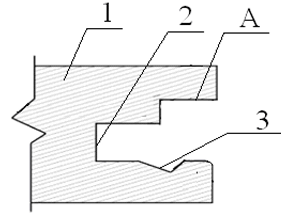
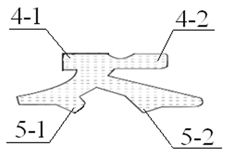
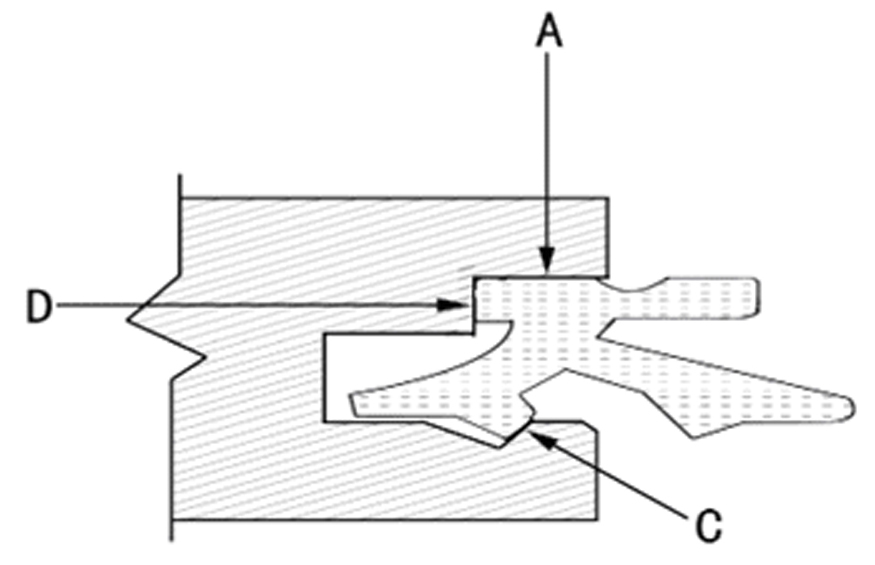
[0034] refer to figure 1 , 2 , this embodiment includes a floor body 1 and a connector body, the peripheral side of the floor body 1 is provided with grooves 2 of the same shape and size, and one side of the groove 2 is provided with an indented locking groove 3; the connector Main tongue I4-1 and main tongue II4-2 are respectively arranged on both sides of the main body, and the main tongue I4-1 and main tongue II4-2 are all adapted to the side groove 2 around the floor body, and the lower part of the connector body Sub-tongue Ⅰ5-1, sub-tongue Ⅱ5-2 are respectively provided, and sub-tongue Ⅰ5-1 and sub-tongue Ⅱ5-2 are all compatible with the inset locking groove 3 on the side of the side groove 2 around the floor body match.

[0035] The fit between the auxiliary tongue I5-1 and the auxiliary tongue II5-2 and the inset locking groove on the side of the peripheral side groove of the floor body is an interference fit.

[0036] The upper end surfaces of the main tongue I4-1 ...

Embodiment 2

[0042] refer to figure 1 , 5 , the difference between this embodiment and embodiment 1 is that the shape of the connector is like " ⊥ " shape, and the material is hard wood, and the floor body is rectangular, and the material is reinforced wood. All the other are the same as embodiment 1.

Embodiment 3

[0044] refer to Image 6 , 7 The difference between this embodiment and Embodiment 1 is that the side grooves around the floor body are trapezoidal grooves, the material of the floor body is cork, and the shape of the connectors is trapezoidal. All the other are with embodiment 1.


PUM


Abstract

The invention discloses a plate paneling locking system, comprising a floor body and a connector body. All the peripheral sides of the floor body are provided with grooves with the same shape and size; one side of each groove is provided with a sunken locked groove; a main tenon tongue I and a main tenon tongue II are respectively arranged on two sides of the connector body; both the main tenon tongue I and the main tenon tongue II are adapted with the grooves on the peripheral sides of the floor body; the lower part of the connector body is respectively provided with a secondary tenon tongue I and a secondary tenon tongue II; both the secondary tenon tongue I and the secondary tenon tongue II are adapted with the sunken locked grooves at one side of the grooves on the peripheral side of the floor body. The invention has the advantages of simple structure, convenient installation, firm jointing, high connecting strength, good stability and capability of truly realizing seamless jointing.

Description

technical field [0001] The present invention relates to a board panel locking system. Background technique [0002] At present, most of the floors processed and sold on the market are installed by the two methods of male and female groove assembly suspension type and ground beam fixed type. No matter which method is used, the process is more complicated and the installation is more troublesome. Limited, resulting in weak tenon and groove bite, low connection strength, poor stability, and there are inevitably gaps between the two floors that are spliced ​​together. [0003] Chinese patent CN 02250882.1 discloses a spliced ​​wooden floor connector, which is provided with a pair of tongues protruding in opposite directions on both sides in the length direction, and the two sides of the tongue and the wood floor body in the length direction The tongues and grooves respectively provided on the sides match each other. When this structural connector is used, during the floor inst...

Claims


Application Information

Patent Timeline
IPC IPC(8): E04F15/02
Inventor 丛伟斌
Owner 丛伟斌
Why Eureka
Try Eureka