
Solar vacuum tube type separated liquid circulation generator

A vacuum tube type, liquid circulation technology, applied in the direction of solar thermal power generation, mechanical power generation by solar energy, machine/engine, etc., to achieve high reliability and achieve the effect of industrialization

Inactive Publication Date: 2015-05-20
CHENGDU AONENGPU TECH
View PDF8 Cites 0 Cited by
  • Summary
  • Abstract
  • Description
  • Claims
  • Application Information

AI Technical Summary

Problems solved by technology

Solar vacuum heat collecting tubes are mainly used in solar water heaters, and there is no system that uses solar vacuum heat collecting tubes to collect energy for liquid cycle power generation

Method used


Image

  • Solar vacuum tube type separated liquid circulation generator
  • Solar vacuum tube type separated liquid circulation generator
  • Solar vacuum tube type separated liquid circulation generator

Examples


Embodiment 1

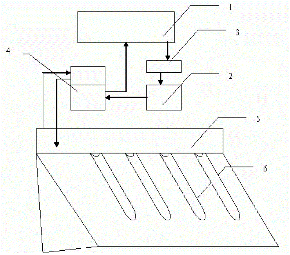
[0043] Embodiment 1. Solar vacuum heat collecting tube liquid cycle power generation system

[0044] Such as figure 1 As shown, a solar vacuum tube with a single opening is used as the collection system, and its thermal energy is used to lift the liquid to complete the power generation of the liquid cycle. Among them, the heat collecting tube of the solar vacuum machine is used as 6 parts of solar energy collection, and a liquid lifting device 4 is used to lift the liquid in the liquid storage box 2, and the liquid is lifted to the working box 1 and then circulated to generate electricity again.

Embodiment 2

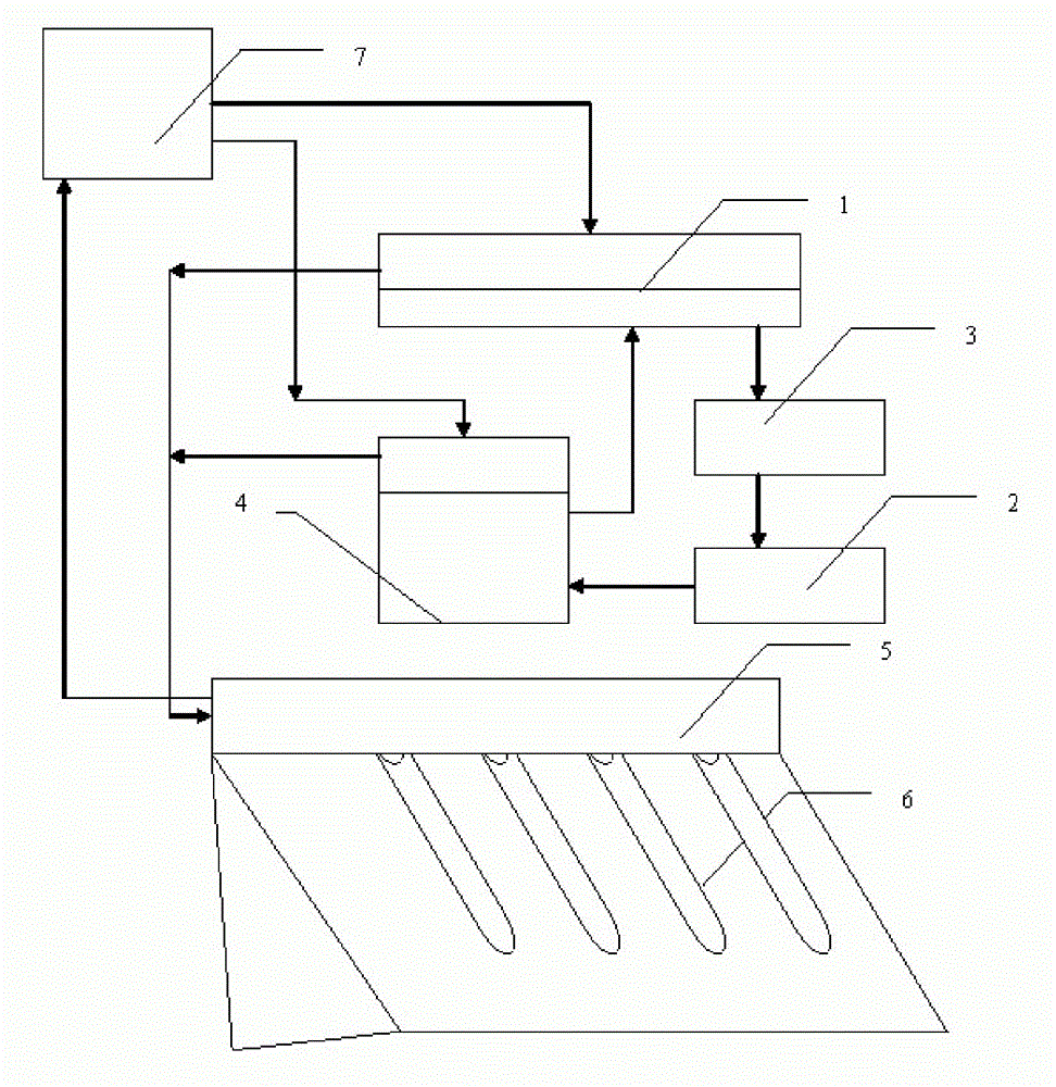
[0045] Embodiment 2. Heat pipe type solar vacuum heat collection tube liquid circulation power generation system

[0046] Such as figure 2As shown, the heat energy collected by the solar energy is used for lifting the liquid and pressurizing the working box and the heat storage box. Among them, the heat pipe type solar energy collection system 1 is adopted, and R245fa or R21 is used as the low-temperature working medium. The piston cylinder structure is adopted in the working box 1 and the liquid lifting device 4, and the gas in the low-temperature working medium box 7 is directly connected with the working box and the liquid. The hoisting device 4 is connected to form a loop, and the solar energy collection system is connected to the low-temperature working medium box to form a loop. The liquid circulates under the heat energy collected by the solar energy collection system and provides pressurization to the working box 1 to achieve high efficiency. generate electricity.

Embodiment 3

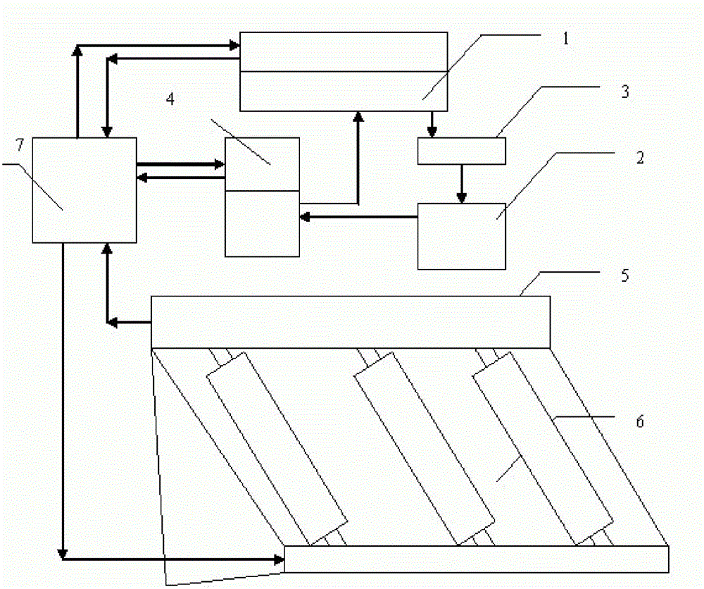
[0047] Embodiment 3. Two-way tube solar vacuum heat collection tube liquid cycle power generation system

[0048] Such as image 3 As shown, in this embodiment, the solar double-way tube is used as the collection part, and the vaporized low-temperature working medium directly enters the low-temperature working box 7, and its condensed liquid enters the vacuum tube from the bottom of the solar double-way tube to realize the The heating of the low-temperature working medium, the heated low-temperature working medium directly lifts the liquid and completes the pressurization of the working box.


PUM


Abstract

The invention provides a separated liquid circulation generator which uses solar vacuum collector tubes as a solar collection system. The separated liquid circulation generator is provided with a working box and a liquid storage box, wherein the working box is separated from the liquid storage box; liquid in the working box drives the liquid generator to generate electricity by the aid of gravitation or pressure; and the liquid enters the liquid storage box after passing through the generator. The solar vacuum collector tubes are utilized to complete the collection of solar energy; and the heat energy of the solar energy is utilized to raise the liquid in the liquid storage box back to the working box, thereby realizing circulating electricity generation. The heat energy collected by a solar collection part is used for pressurizing the working box and the liquid storage box.

Description

technical field [0001] The invention relates to power generation equipment, in particular to liquid circulation power generation equipment using solar vacuum tubes as energy collection systems. Background technique [0002] The existing power generation technology mainly uses steam as the working medium to generate electricity, that is, steam thermal power generation limited by the Carnot cycle through the principle of heat engine. The main working medium is water. The nozzle is set on the stator without movement, and the blades are set on On the rotor, the steam injected by the nozzle pushes the blades to rotate and generate electricity. Due to the condensation process, a large amount of energy is excluded from the cycle, resulting in inefficient energy use. [0003] The Rankine cycle (ORC) generator set using low-temperature organic matter is suitable for low-temperature heat sources and small-scale power generation, but it is still a heat engine of the Carnot cycle, whic...

Claims


Application Information

Patent Timeline
Patent Type & Authority Patents(China)
IPC IPC(8): F03G6/06
CPCY02E10/46
Inventor 李建民
Owner CHENGDU AONENGPU TECH
Learn More