Electrical control device for piston methane slag and methane liquid discharging pump

A discharge pump and piston type technology, which is applied in the field of control devices, can solve the problems of blockage of the discharge pump of the biogas digester, and achieve the effect of convenient discharge, large flux and less failure

Inactive Publication Date: 2010-12-01
HARBIN DEGUANG NEW ENERGY
View PDF4 Cites 0 Cited by
  • Summary
  • Abstract
  • Description
  • Claims
  • Application Information

AI Technical Summary

Problems solved by technology

[0003] The purpose of the present invention is to solve the problem of clogging of the discharge pump of the existing biogas digester, and provide an electric control device for the piston type biogas residue and biogas liquid discharge pump

Method used


Image

  • Electrical control device for piston methane slag and methane liquid discharging pump
  • Electrical control device for piston methane slag and methane liquid discharging pump
  • Electrical control device for piston methane slag and methane liquid discharging pump

Examples


specific Embodiment approach 1

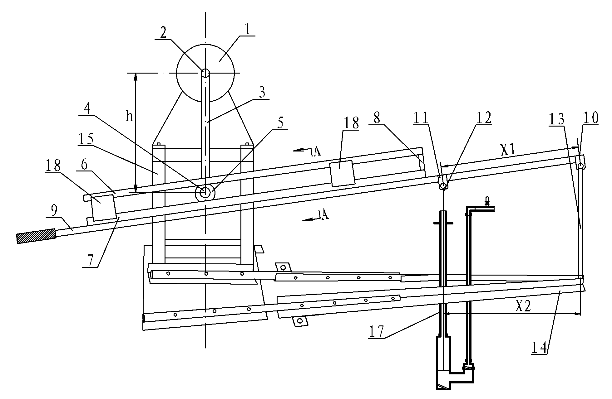
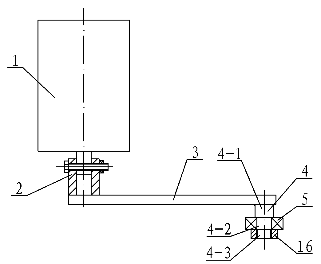
[0007] Specific implementation mode one: combine Figure 1 to Figure 4 Describe this embodiment, this embodiment includes motor 1, sleeve 2, rocker arm 3, crank 4, bearing 5, upper slide rail frame 6, glide rail frame 7, support plate 8, pressure handle 9, first hinge seat 10 , the second hinged seat 11, steel bar 12, pole 13, fixed frame 14, motor seat 15, lock nut 16 and at least two short channel steels 18, the motor 1 is fixed on the motor seat 15, the first hinged seat 10 and the second hinge seat 11 are sequentially installed on the press handle 9 along the direction from the front end to the rear end of the press handle 9, the distance X1 between the first hinge seat 10 and the second hinge seat 11 is 300 mm to 1000 mm, and the sleeve 2 is set on the On the output shaft of the motor 1, the sleeve 2 and the motor 1 are connected together by connecting elements, one end of the rocker arm 3 is fixedly connected to the sleeve 2, the other end of the rocker arm 3 is welded t...

specific Embodiment approach 2

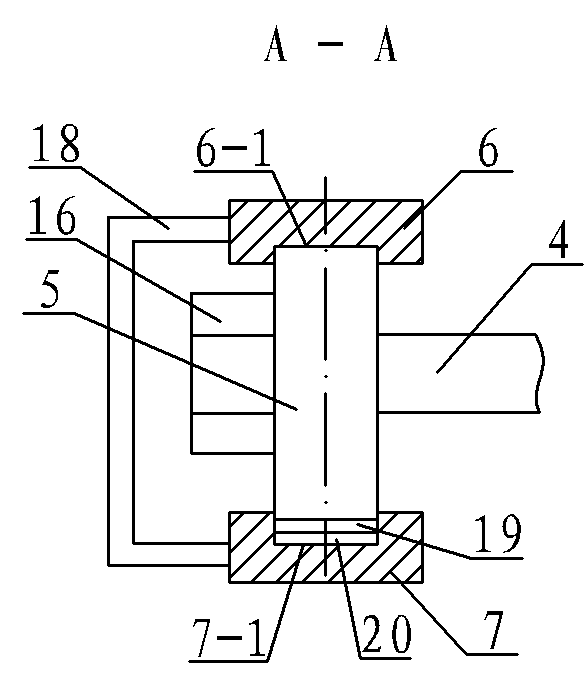
[0008] Specific implementation mode two: combination image 3 This embodiment is described. The difference between this embodiment and the first embodiment is that it also adds a gasket 19, and the gasket 19 is arranged in the glide path 7-1. The surface finish of the gasket 19 is high, and when the bearing 5 rolls on the smooth gasket 19, the frictional resistance is small. Other components and connections are the same as those in the first embodiment.

specific Embodiment approach 3

[0009] Specific implementation mode three: combination image 3 Describe this embodiment, the difference between this embodiment and specific embodiment one is that it also adds polyethylene foam 20, and polyethylene foam 20 is arranged in glideway 7-1, and is positioned at pad 19 and bottom surface of glideway 7-1 between. The polyethylene foam 20 plays the role of sound-absorbing. Other components and connections are the same as those in the second embodiment.

[0010] The working principle of the present invention: the sleeve 2 rotates under the drive of the motor 1, the sleeve 2 drives the rocker arm 3 to perform a circular motion around the output axis of the motor 1, the crank 4 and the bearing 5 move accordingly, when the bearing 5 rotates to the highest point, the piston in the discharge pump moves to the highest point, and when the bearing 5 turns to the lowest point, the piston in the discharge pump moves to the lowest point, and the bearing 5 rotates 360° around t...


PUM


Abstract

The invention discloses an electrical control device for a methane slag and methane liquid discharging pump and relates to a control device for a discharging pump, which aims to solve the problem of the blockage of the conventional discharging pump of a methane tank. A first hinged seat and a second hinged seat are arranged on a pressing handle along the direction from the front end to the rear end of the pressing handle in turn; a sleeve is sleeved on an output shaft of a motor; one end of a rocker arm is fixedly connected with the sleeve, while the other end is welded with the end face of acrank; a bearing is sleeved on the crank; a support plate is arranged one end of the space between an upper slideway frame and a lower slideway frame; an upper slideway on the upper slideway frame isopposite to a lower slideway on the lower slideway frame; at least two short steel channels are respectively buckled on the side of the frames and positioned on the side corresponding to the crank; the lower end face of the lower slideway frame is fixedly connected with the upper end face of the pressing handle; the bearing is arranged on the upper slideway and the lower slideway; the upper end of a strut is hinged with the first hinged seat, while the lower end is fixedly connected with a fixed mount; and the upper end of a reinforcing steel bar is hinged with the second hinged seat. The electrical control device is used on the methane slag and methane liquid discharging pump.

Description

technical field [0001] The invention relates to a control device for a discharge pump. Background technique [0002] At present, the discharge device of the biogas digester usually uses a negative pressure centrifugal pump to discharge the material. During the discharge process, it is easy to be blocked by large particles of biogas residue or high-concentration residue liquid, and it is very difficult to clean the blockage. In order to solve the above problems, in the discharge pump A blade is installed at the feed inlet. The blade cuts hard but not soft. The large particles of biogas residue in the biogas tank are much softer, and the blade is difficult to function. Therefore, the problem of the blockage of the discharge pump has not been fundamentally solved. Contents of the invention [0003] The object of the present invention is to provide an electric control device for the piston-type biogas residue and biogas slurry discharge pump to solve the problem of blockage of...

Claims


Application Information

Patent Timeline
Patent Type & Authority Applications(China)
IPC IPC(8): F04B49/06
Inventor 高德广杜玉歧
Owner HARBIN DEGUANG NEW ENERGY
Why Eureka
Try Eureka