Experimental device for projectile motion study capable of displaying time in real time

A time display and experimental device technology, applied in the field of experimental devices for projectile motion research, can solve the problems of insufficient time value basis, time value error, lack of convincing, etc., to avoid incomplete display, easy to grasp, no drag shadow effect

Inactive Publication Date: 2010-12-01
ZHEJIANG UNIV
View PDF4 Cites 5 Cited by
  • Summary
  • Abstract
  • Description
  • Claims
  • Application Information

AI Technical Summary

Problems solved by technology

Obviously, the basis for such a time value is not sufficient, and the non-experimental operator

Method used


Image

  • Experimental device for projectile motion study capable of displaying time in real time
  • Experimental device for projectile motion study capable of displaying time in real time
  • Experimental device for projectile motion study capable of displaying time in real time

Examples


Embodiment Construction

[0021] Below in conjunction with accompanying drawing, the present invention will be further described:

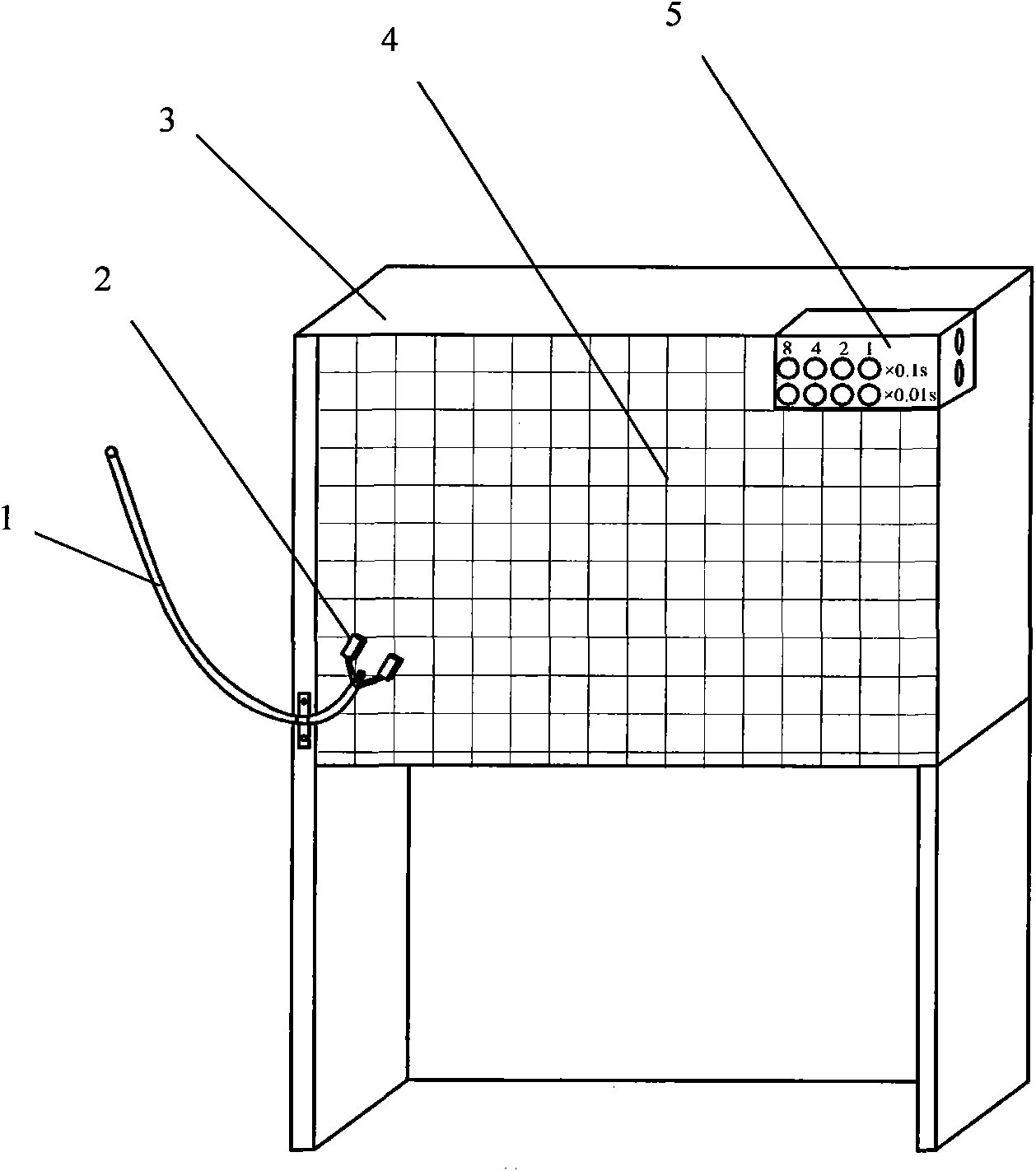
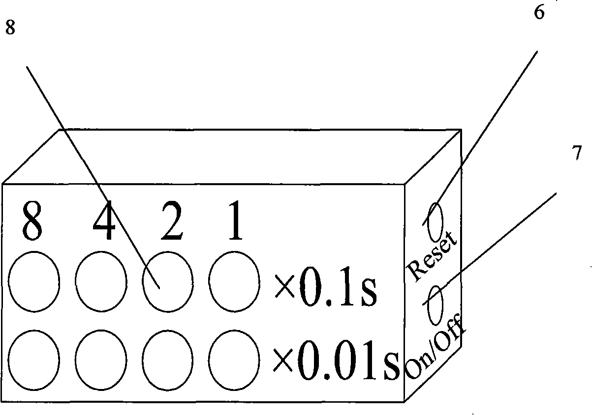
[0022] Such as figure 1 As shown, the experimental device for the research of projectile motion that can be displayed in real time includes a shooting light box 3, a glass panel 4, a projectile tube 1, a photoelectric gate 2, a time display 5, a digital camera and a tripod, and the glass panel 4 is installed on the front of the shooting light box 3 , fix the projection tube 1 on the left frame of the shooting light box 3, the two sides of the nozzle of the low end of the projection tube 1 are pressed with a photoelectric gate 2, the upper right position of the shooting light box 3 is embedded in the installation time display 4, the digital camera is fixed on the tripod, and the lens faces Shoot Lightbox 3. The projecting tube is an asymmetrical U-shaped hollow tube with an inner diameter of 15-20 mm and a height difference between two ends of the tube greater than 0.5 met...


PUM

PropertyMeasurementUnit
The inside diameter ofaaaaaaaaaa

Abstract

The invention discloses an experimental device for projectile motion study capable of displaying time in real time, which comprises a photographic lamp house, a glass panel, a projecting pipe, a photoelectric door, a time display, a digital camera and a tripod, wherein the glass panel is arranged on the front surface of the photographic lamp house; the projecting pipe is fixed on the left frame of the photographic lamp house; the photoelectric door is arranged at two sides of a pipe orifice at the low end of the projecting pipe; the time display is embedded into the upper right part of the photographic lamp house; the digital camera is fixed on the tripod; and a lens faces towards the photographic lamp house. When a small ball is ejected out of the pipe orifice at the low end of the projecting pipe to pass through the photoelectric door, the time display automatically starts timing, and the digital camera captures video of the whole projectile motion process of the small ball taking grid coordinates as a background, thus acquiring clear image, being capable of accurately reading X and Y coordinates, achieving high timing precision up to 0.01 second and being free from influence of ambient brightness while shooting. The experimental device has the advantages of short exposure time of the camera, no trails in the captured image, simple structure and high reliability, thus providing very convenient experimental conditions for studying projectile motion.

Description

technical field [0001] The invention relates to an experimental device for researching projectile motion, in particular to an experimental device for researching projectile motion which can be displayed in real time. Background technique [0002] In order to enable science and engineering students to deepen their understanding of the principle of independence of motion, students are arranged to conduct experimental research on the motion of projectiles in university physics experiments. The experiment usually uses a graph paper as the background to throw a small ball, and uses a camera to capture the trajectory of the ball. , and then use the instantaneous position data of the ball's trajectory in the photo, including the X coordinate, Y coordinate and time t at this position, to write its motion equations in the X direction and Y direction respectively to explore the law of motion of the ball. In the era of film cameras, the multiple exposure method is used to obtain the in...

Claims


Application Information

Patent Timeline
IPC IPC(8): G09B23/10
Inventor 蒋卫建陈一新夏姣贞顾智企
Owner ZHEJIANG UNIV
Why Eureka
Try Eureka